- About Us

- Our Services
- Your Industry
- Resources
- News & Blog
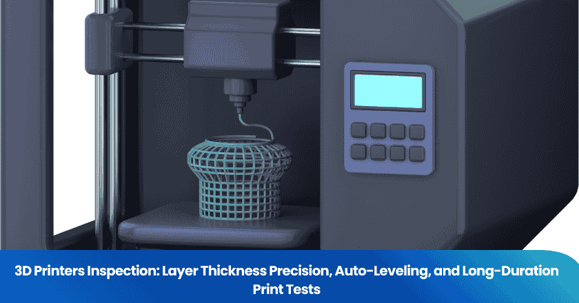
A 3D printer that works for the first fifteen minutes is not the same as one that works reliably for an eight-hour production run. Yet most factory functional tests for 3D printers consist of little more than a short sample print that confirms the machine turns on and moves. Three specific test categories — layer thickness precision measurement, auto-leveling system verification, and long-duration print stability testing — address the failure modes that brief functional testing systematically misses. For buyers importing FDM or resin 3D printers from Chinese manufacturers, understanding what these tests reveal and how to specify them is the foundation of a pre-shipment inspection that actually protects product quality.
Key Takeaways
- Layer thickness precision is controlled by Z-axis accuracy — measured by printing a calibration cube and verifying the actual height against the programmed height with calipers. A ±0.3–0.5 mm error on a 100 mm object is a common threshold, but buyers sourcing printers for precision applications should specify tighter tolerances.
- Auto-leveling (ABL) system verification requires a full-bed single-layer test print that physically reveals whether the mesh compensation grid is functioning correctly — a passed sensor calibration routine is not sufficient proof.
- Long-duration print stability testing (minimum 4 hours) is the only method that reliably surfaces failure modes such as layer shifting, under-extrusion, print detachment, thermal protection cutouts, and power supply degradation that occur only after the printer reaches thermal equilibrium under sustained load.
Layer Thickness Precision: What Controls It and How to Measure It
The Z-Axis as the Primary Precision Variable
In FDM (Fused Deposition Modeling) 3D printing, layer thickness is determined by the Z-axis motion system. The printer is commanded to raise the print head or build platform by exactly the programmed layer height — typically 0.1 mm to 0.3 mm — between each layer. The precision with which this movement is executed depends on the quality and calibration of the Z-axis lead screw, the stepper motor step resolution, anti-backlash compensation in the mechanical assembly, and the accuracy of the firmware's steps-per-mm calibration value.
Several mechanical failure modes degrade Z-axis precision. Backlash in the lead screw and nut — play in the linear motion system that allows a small amount of uncontrolled movement at the start of each new direction of travel — causes layer thickness to vary systematically rather than randomly. This appears in the printed output as Z-banding: visible horizontal lines or ridges on otherwise smooth surfaces, spaced at the pitch of the lead screw's mechanical play. A worn or poorly lubricated lead screw produces inconsistent step-to-step motion that manifests as irregular layer spacing. Insufficient current to the Z-axis stepper motor causes step loss — the motor skips steps under load, producing a sudden permanent Z-offset that shifts all subsequent layers.
How to Measure Layer Thickness Precision
The standard method for measuring layer thickness precision is the calibration cube test. The inspector programs and prints a simple cube with known nominal dimensions — typically 20 mm × 20 mm × 20 mm for a quick test, or 100 mm × 100 mm × 100 mm for a more rigorous dimensional accuracy check. After the print cools and is removed from the bed, the actual height of the cube is measured with digital calipers across multiple points on the top surface. The deviation between the measured height and the programmed height directly reflects the Z-axis accuracy.
For buyers sourcing general-purpose FDM printers for prototyping or industrial use, a common acceptable threshold is ±0.3–0.5 mm error on a 100 mm test cube. For buyers sourcing printers for precision manufacturing applications — dental models, engineering components, jigs and fixtures — the tolerance should be tighter, typically ±0.1–0.2 mm on 100 mm. These thresholds must be specified in the purchase agreement and inspection brief. A printer that ships without an agreed dimensional tolerance has no contractual quality baseline.
What Layer Thickness Defects Look Like
Beyond the calibration cube measurement, a visual inspection of a multi-layer test print reveals layer thickness quality issues that calipers alone do not capture. Z-banding appears as regular horizontal ridges on smooth surfaces — a repeating pattern at the frequency of the lead screw pitch. Systematic Z-offset — where all layers are consistently thicker or thinner than programmed — shows up as the print being taller or shorter than its design dimension. Layer adhesion failures, where individual layers do not bond properly to adjacent layers, appear as delamination lines that can be mechanically separated with minimal force — a sign of insufficient heat, incorrect layer height, or under-extrusion that compounds over multiple layers into a structural weakness.
Auto-Leveling System Verification
What Auto-Bed Leveling Does — and What It Doesn't Guarantee
Automatic bed leveling (ABL) systems use a sensor — typically inductive, capacitive, or mechanical (BLTouch) — to probe the build surface at multiple points in a grid pattern before each print begins. The measured height values at each probe point are used to construct a mesh compensation map of the bed surface. During the print, the firmware applies continuous micro-adjustments to the Z-axis to follow the topography of this mesh, compensating for bed tilt, surface warping, and minor irregularities in the build platform.
The critical point for pre-shipment inspection is this: a printer that successfully completes its ABL calibration routine has demonstrated that the probe sensor is working and that the firmware has generated a mesh. It has not demonstrated that the mesh is accurate, that the probe trigger point is correctly calibrated, or that the first layer is being deposited at the intended height across the full build surface. A mis-calibrated Z-offset — the distance between the probe trigger point and the nozzle tip — will cause the printer to deposit the first layer at a consistently incorrect height, regardless of how accurate the mesh compensation is.
How to Verify Auto-Leveling Performance
The only definitive test of ABL system performance is a full-bed single-layer test print. The inspector prints a large, single-layer rectangle or grid pattern covering the maximum usable build area — for a 300 mm × 300 mm printer, this means printing a single-layer pattern that reaches to the corners and edges of the bed. The inspector then physically examines the first layer across the entire print area.
A properly functioning ABL system should produce a first layer that shows consistent filament width and adhesion from corner to corner. Signs that ABL compensation is inadequate include: corners or edges where the filament does not adhere to the bed surface, indicating the nozzle was too far from the bed at that point; areas where filament is crushed too thin or compressed into a wide ribbon, indicating the nozzle was too close; and visible transitions in filament width corresponding to transitions between mesh compensation zones. For a more rigorous test, the inspector can deliberately de-level the bed by a small known amount at one corner before the test print, verify that the ABL system compensates correctly in the printed output, then restore the original configuration.
ABL Probe Density and Its Impact on Quality
The density of the ABL probe grid determines how precisely the mesh captures the actual surface topography. A 3×3 probe grid (9 points) provides coarse compensation — adequate for a small, flat, well-manufactured bed but insufficient for a large-format printer with thermal deformation. A 5×5 grid (25 points) or higher, such as the 49-point grids used on some large-format printers, produces a detailed topographic map that enables accurate compensation even for warped surfaces. For buyers sourcing printers intended for production use, the ABL probe grid density should be specified, and the inspector should verify during the first-layer test that compensation quality at the bed edges is comparable to the center — edges are where coarse grids most often show inadequate compensation.
Long-Duration Print Stability Testing
Why Long Prints Fail Differently Than Short Tests
A 3D printer that successfully completes a 20-minute sample print at the factory can still contain defects that reliably cause failures in production jobs of 4, 8, or 12 hours. The failure modes that only emerge under sustained operation are categorically different from the failures that appear in brief testing. They fall into two groups: thermal stabilization failures, where the printer's performance changes as components reach their steady-state operating temperature; and cumulative mechanical failures, where small errors compound across hundreds or thousands of layers until the print fails.
Long-Duration Failure Mode Reference
| Failure Mode | When It Appears | Root Cause | What to Look For |
|---|---|---|---|
| Layer Shifting | Typically after 30–90 minutes of continuous printing | Belt slip or stretch; stepper motor overheating causing step loss; loose pulleys | Horizontal offset between print layers above the failure point — the print continues but all subsequent layers are offset in X or Y |
| Under-Extrusion | Gradual onset after 1–3 hours | Partial nozzle clog from prolonged high-temperature exposure; extruder gear wear; heat creep from inadequate cooling | Sparse or missing filament in upper layers; thin, weakened wall sections; gaps in infill |
| Print Detachment | Can occur at any height, often after thermal stabilization | Bed adhesion failure from incorrect bed temperature maintenance; thermal stress in the part; inadequate first-layer adhesion from ABL miscalibration | Part lifts at corners or detaches completely from the print surface; spaghetti printing above the detachment point |
| Thermal Protection Cutout | Typically 1–4 hours into print | Thermistor degradation or loose connection triggering runaway protection; PID tuning inadequate for sustained operation; cooling fan degradation at temperature | Print stops abruptly with thermal error or "heating failed" fault code; printer may cool to safe temperature and halt |
| Power Supply Sag | After 2+ hours under full load | Undersized or marginal power supply unit operating near rated capacity for extended periods; voltage sag under simultaneous heated bed, hotend, and motor load | Temperature instability, step loss, or stepper motor stalling due to insufficient drive voltage; power supply fan running at full speed continuously |
How to Conduct a Long-Duration Print Stability Test
The standard long-duration stability test for 3D printer pre-shipment inspection uses a test model designed to stress the printer across multiple dimensions simultaneously. The test model should be tall enough to require at least 4 hours to print at normal print speed, should include both solid and sparse-infill sections to exercise the extruder across different deposition rates, and should span a reasonable portion of the build volume in X and Y to exercise both motion axes. A tall calibration tower or a 50% scale model of a complex part are both suitable test geometries.
The inspector monitors the print throughout its duration, observing for any of the failure modes in the table above. Critically, the test print should be examined after completion for dimensional accuracy: the height of the completed print should be measured with calipers and compared against the programmed height to verify that the Z-axis maintained precision throughout the full print duration. Surface quality inspection of the upper layers compared to the lower layers confirms whether under-extrusion or thermal changes degraded quality as the print progressed.

3D printer pre-shipment inspection workflow: from visual inspection and Z-axis calibration through ABL verification and long-duration print stability testing.
Building a Complete 3D Printer Pre-Shipment Inspection
Inspection Sequence and Timing
A well-structured 3D printer pre-shipment inspection typically follows this sequence. First, visual and mechanical inspection: verify frame assembly integrity, linear rail and rod condition, belt tension and pulley alignment, cable management, and all electrical connections. Second, Z-axis calibration cube print and dimensional measurement. Third, ABL full-bed single-layer test print with visual analysis of first-layer quality across the build surface. Fourth, long-duration print stability test — this is the longest phase and typically runs 4 hours minimum. During the stability test, the inspector conducts visual monitoring at regular intervals rather than continuous observation. Fifth, dimensional measurement and surface quality assessment of the completed long-duration print. Sixth, documentation of all findings and pass/fail disposition.
AQL Sampling for Volume Orders
For buyers importing a volume order of 3D printers — for example, 50 or 200 units for distribution, education, or industrial deployment — 100% long-duration testing of every unit is cost-prohibitive. The practical approach is AQL sampling per ISO 2859-1 for the long-duration stability test, combined with 100% visual inspection and 100% short-function testing of all units in the shipment. At General Inspection Level II and AQL 2.5 for a shipment of 100 printers, the required sample size for the long-duration test is approximately 32 units. If more than 2 of the 32 sampled printers fail the long-duration test, the lot is held for investigation.
For the calibration cube and ABL tests, a higher sampling rate — at least 50% or full sample — is practical because these tests take only 20–40 minutes per printer. Buyers ordering printers for high-stakes applications (production facilities, professional services) should specify 100% calibration cube and ABL verification with AQL-sampled long-duration testing.
TradeAider's pre-shipment inspection service provides an Online Real-Time Report accessible during the inspection, allowing buyers to monitor layer calibration measurements and stability test progress in real time. The Official PDF Report is delivered within 24 hours with complete test documentation including dimensional measurement data, ABL test photos, and stability test observations.
Frequently Asked Questions
What layer thickness tolerance should buyers specify for a 3D printer pre-shipment inspection?
The appropriate tolerance depends on the intended application. For general prototyping and hobbyist-grade printers, a dimensional accuracy of ±0.5 mm on a 100 mm calibration cube is a practical threshold. For desktop engineering printers marketed for dimensional accuracy and mechanical fit testing, ±0.2 mm on 100 mm is a more appropriate requirement. For printers marketed as suitable for dental, jewelry, or precision industrial applications, ±0.1 mm or tighter may be necessary. These figures apply to the overall height measurement from the Z-axis; X and Y dimensional accuracy depends on the belt and pulley system and should also be specified and tested separately using the width and depth measurements of the same calibration cube. The key principle is that the tolerance must be agreed upon before the inspection — not inferred from the manufacturer's marketing language after goods arrive.
Is a passed ABL calibration routine sufficient proof that auto-leveling is working?
No — and this is one of the most common inspection gaps in basic factory testing. A completed ABL routine confirms that the probe sensor triggered at each mesh point and that the firmware stored the resulting height values. It does not verify that the Z-offset between the probe trigger point and the actual nozzle height is correctly calibrated, that the mesh compensation values are accurate, or that the first layer is being deposited at the correct height across the full build surface. The only valid verification is a physical first-layer test print covering the full build area, examined visually for consistent filament adhesion and width. For buyers whose application depends on first-layer adhesion quality — such as parts requiring a specific surface finish on the build-plate face — the ABL full-bed test print is a mandatory inspection element. For help estimating the cost of including this test in a pre-shipment inspection, use TradeAider's Inspection Charge Calculator.
How long should a long-duration print stability test run for 3D printer inspection?
A minimum of 4 hours is the practical baseline for a pre-shipment stability test. This is long enough to surface thermal stabilization failures (which typically appear after 30–90 minutes), early onset under-extrusion from heat creep or extruder gear wear (which typically appears after 1–3 hours), and power supply sag under sustained load. For printers that will be used in production environments with regular 8-hour or multi-day print jobs, extending the stability test to 6–8 hours provides greater confidence. The long-duration test model should be selected to produce a measurable, dimensional artifact — not just a demonstration model — so that post-print caliper measurement can confirm Z-axis precision was maintained throughout the full test duration. If a printer consistently produces correct calibration cubes at minute 1 but measures out of tolerance at the completion of a 4-hour stability print, it has a thermal drift problem that will cause dimensional failures in any production job exceeding a few hours.
What should buyers do if the long-duration print stability test fails?
A stability test failure — whether from layer shifting, under-extrusion, thermal cutout, print detachment, or dimensional drift — should trigger a hold on the entire shipment and a formal corrective action request to the supplier. The failure mode identified during the stability test usually points to a specific root cause: layer shifting points to motion system issues (belt, stepper motor, pulley), under-extrusion points to hotend or extruder issues, and thermal cutout points to temperature sensing or cooling system defects. The supplier should diagnose the root cause, implement corrective action at the production or QC level, and demonstrate resolution through re-testing before the hold is released. Accepting a shipment with known stability test failures — even with a price concession — typically results in customer complaints and returns that cost far more than the concession value. For buyers evaluating a new 3D printer supplier for the first time, combining a factory audit to assess the manufacturer's QC capability with a pre-shipment inspection of the first production batch provides end-to-end supply chain quality coverage.
A 3D printer that passes a brief factory function test can still fail systematically in production — through Z-axis drift that undermines dimensional accuracy, ABL miscalibration that ruins first-layer adhesion, or a thermal or mechanical failure mode that only surfaces after hours of continuous operation. TradeAider's pre-shipment inspection service can be scoped to include layer thickness calibration, ABL full-bed verification, and long-duration print stability testing, with real-time reporting and an official report within 24 hours. Use the Inspection Charge Calculator to estimate costs, or contact TradeAider to design a 3D printer inspection scope matched to your order volume and application requirements.
Related Articles

Grow your business with TradeAider Service
Click the button below to directly enter the TradeAider Service System. The simple steps from booking and payment to receiving reports are easy to operate.