- About Us

- Our Services
- Your Industry
- Resources
- News & Blog
A capacitor or resistor that measures within spec at room temperature on the factory floor is not the same as one that holds its value under load at 85°C, or one that survives a voltage surge without breaking down. For buyers sourcing electronic assemblies or passive components from Chinese manufacturers, the gap between what passes a basic visual check and what will survive in the field is where most quality problems hide. Tolerance screening and dielectric withstanding voltage (DWV) testing are the two disciplines that close that gap — and both can be applied systematically at the incoming inspection stage, long before a board goes into production.
Key Takeaways
- Capacitor tolerance grades range from ±1% (COG/NP0) to ±20% (standard electrolytics) — the grade that matters depends on your circuit's sensitivity, not just cost.
- Dielectric withstanding voltage (DWV) testing applies a voltage significantly above the rated working voltage to verify that insulation will not break down under real-world surges.
- Counterfeit passive components frequently carry incorrect values or recycled dielectrics that pass visual checks but fail under electrical stress — incoming inspection must include electrical measurement, not just visual review.
Why Tolerance and Voltage Ratings Both Matter
Tolerance Codes and What They Tell You
Tolerance in a passive component describes the allowable deviation from its nominal value. For resistors and capacitors, the industry uses the EIA E-series preferred values: E6, E12, E24, E48, E96, and E192, where a higher series number corresponds to a tighter tolerance and more available values per decade. An E6 resistor carries ±20% tolerance; an E96 part carries ±1%.
For capacitors, tolerance grades are identified by letter codes. COG/NP0 ceramic capacitors are available in ±1% (F grade) as standard catalog items, making them the default choice for precision filter, timing, and RF circuits where both initial accuracy and long-term stability are required. X7R and X5R ceramics are typically specified at ±10% (K grade) as standard, with ±5% available at modest premium. Standard aluminum electrolytic capacitors carry ±20% tolerance, and tight-tolerance electrolytics at ±10% represent the practical limit for most series.
Resistors follow a comparable hierarchy. Metal film resistors — the dominant type in modern PCB designs — are widely available in the E96 series at ±1% tolerance, with ±0.1% available for precision instrumentation, aerospace, and medical applications. In applications where accuracy is non-negotiable — such as aerospace, automotive, or medical electronics — precision components with tolerances of 0.1% or better are standard practice, though at higher cost.
The Hidden Cost of Out-of-Tolerance Parts
The financial case for tolerance screening at incoming inspection is straightforward: a resistor with a labeled ±1% tolerance that actually measures ±5% because it has been mis-sorted, remarked, or substituted will pass visual inspection every time. In a voltage divider circuit, mismatched resistor values produce incorrect output voltages. In an RC timing circuit — a 555 timer monostable, a microcontroller external RC oscillator, an op-amp integrator — capacitor tolerance translates directly and linearly into timing accuracy. A timing capacitor with ±20% tolerance produces ±20% timing variation before any other error source is considered.
The compounding effect matters. A circuit relying on both a ±5% resistor and a ±10% capacitor faces a worst-case timing range of roughly ±15%, before temperature and voltage coefficient contributions are added. Catching this at incoming inspection costs minutes. Catching it after field deployment costs orders of magnitude more.
Tolerance Screening Methods for Incoming Inspection
Capacitor Tolerance Screening
Capacitance measurement using an LCR meter is the primary electrical test at incoming inspection. For standard SMD ceramic capacitors, this measurement should be made at the test voltage specified by the manufacturer — typically 1.0 ±0.2 Vrms for most dielectrics. Class II dielectrics (X7R, X5R) experience a measurable decrease in capacitance with applied DC bias voltage — an X7R capacitor can derate by as much as 3% in capacitance after DC withstanding voltage testing, which means any measurement taken under different bias conditions than the manufacturer's specification will yield misleading results.
Beyond capacitance, two additional parameters should be checked during incoming inspection of capacitors:
Dissipation Factor (DF) / Equivalent Series Resistance (ESR): High ESR values indicate degraded performance even when capacitance reads within tolerance. This is particularly relevant for electrolytic capacitors destined for power supply filtering, where high ESR causes voltage ripple and thermal instability. For large electrolytic capacitors, ESR values above 1Ω flag a performance problem regardless of capacitance reading.
Insulation Resistance (IR): Leakage current under DC bias reveals dielectric quality. Variations in insulation resistance can occur due to changes in surface resistivity from moisture or contaminants, and changes in bulk dielectric resistivity from improper formulation or structural defects including voids, cracks, or delaminations. A capacitor that shows acceptable capacitance but elevated leakage current has a compromised dielectric.
Resistor Tolerance Screening
Resistance measurement with a calibrated precision ohmmeter or four-wire Kelvin measurement (for values below ~10Ω) is the standard incoming check. For SMD resistors, the marking on the body must be cross-referenced against the purchase order before measurement: ultra-miniature packages including 0201 and 01005 carry no markings whatsoever due to insufficient printable surface area, making incoming inspection verification by electrical test the only reliable method for value confirmation.
Temperature coefficient of resistance (TCR) is a secondary parameter relevant for precision applications. Metal film resistors in the E96 series typically carry TCR values of ±50 to ±100 ppm/°C; precision thin-film types can reach ±5 to ±25 ppm/°C. If a supplier provides metal film parts marked as thin-film precision, TCR measurement over a temperature sweep will expose the substitution — a test visual inspection cannot perform.
Where AQL Sampling Applies
For shipments of passive components in volume, 100% electrical testing of every unit is generally not practical outside of high-reliability or military procurement contexts. The standard incoming inspection approach applies AQL (Acceptance Quality Limit) sampling — testing a statistically determined sample size against a defined acceptable quality level, and accepting or rejecting the lot based on the number of defects found in the sample. AQL sampling calculators allow you to determine the appropriate sample size for your lot quantity and quality threshold.
For passive components procured from authorized distributors with full traceability to the original component manufacturer (OCM), a reduced inspection level is typically appropriate. For components sourced through brokers, gray-market channels, or suppliers without verifiable OCM traceability, a tighter AQL and additional electrical testing beyond basic tolerance measurement are warranted. TradeAider's inspection standard documentation outlines the sampling methodologies applicable to electronic component inspection.
Tolerance Grade Comparison by Component Type
| Component Type | Standard Tolerance | Tight Tolerance | Key Screening Test | Typical Application |
|---|---|---|---|---|
| COG/NP0 Ceramic Cap | ±5% | ±1% | LCR meter at 1.0 Vrms | RF, precision timing, filters |
| X7R/X5R Ceramic Cap | ±10% | ±5% | LCR meter + DC bias check | Decoupling, bypassing |
| Aluminum Electrolytic Cap | ±20% | ±10% | Capacitance + ESR | Power supply bulk filtering |
| Metal Film Resistor | ±1% | ±0.1% | 4-wire resistance measurement | General purpose, precision dividers |
| Thin-Film Precision Resistor | ±0.1% | ±0.01% | Resistance + TCR sweep | Medical, aerospace, measurement |
| Film Capacitor (MKP/MKT) | ±5–10% | ±1–2% | LCR meter (no DC voltage coefficient) | Precision timing, audio, power factor |
Voltage Withstand Testing (DWV / Hipot)
What DWV Testing Measures
Dielectric Withstanding Voltage (DWV) testing — also called hipot testing, high-potential testing, or dielectric strength testing — applies a voltage significantly higher than the component's rated working voltage to verify that the insulating material will not break down under real-world conditions. The test is designed to account for momentary over-voltages caused by switching, surges, and other transient phenomena that components will encounter in normal operation. During the test, leakage current is monitored; a spike above the specified limit indicates dielectric failure.
The DWV test consists of applying a voltage significantly higher than the rated voltage for a specific time between mutually insulated portions of a component or between insulated portions and ground. For connectors, cables, and transformer windings, the test voltage is applied across the insulation. For capacitors, the dielectric layer itself is the material under test.
The standards governing DWV testing across component types include IEC 60243 (dielectric strength of solid insulating materials), ASTM D149 (test methods for dielectric breakdown voltage), and MIL-STD-202 for military and high-reliability components. For PCB assemblies, IPC/WHMA specifications define class-based requirements.
Test Voltage Levels and Pass/Fail Criteria
Understanding the relationship between working voltage, test voltage, and breakdown voltage is essential for setting pass/fail criteria correctly. DWV is derived from breakdown voltage (BDV) by the relationship DWV = 0.75 × BDV, and working voltage is approximately 1/3 × DWV or 0.25 × BDV. In practice, this means a component with a 1000 VAC breakdown voltage has a DWV test voltage of 750 VAC, and a rated working voltage of 250 VAC. The test is applied for 60 seconds with no indication of arcing as the pass criterion.
For PCB assemblies, IPC/WHMA specifications recommend a leakage current limit of 1 mA at 1000 VDC for Class 2 assemblies (dedicated service products requiring extended life) and 1 mA at 1500 VDC for Class 3 assemblies (high-performance products where equipment downtime cannot be tolerated). Setting the limit significantly below these levels causes false failures by confusing normal capacitive charging current with dielectric breakdown.
A common production spec for assembled boards requires the product to withstand voltages equal to approximately twice the normal operating line voltage plus 1000 volts for a defined dwell time. For example, a 230V AC product would face a test voltage of approximately 2,460 VAC — well above any transient it will encounter in service.
Burn-In Testing for High-Reliability Applications
For multilayer ceramic capacitors (MLCCs) going into aerospace, military, or medical applications, standard DWV testing is supplemented by burn-in — an accelerated life stress test that screens out latent defects before components are assembled. Burn-in for MLCCs is typically performed at twice the working voltage rating at 85°C or 125°C for durations of 96, 100, or 168 hours, per MIL-C-55681, MIL-C-123, and MIL-C-49467. Units are monitored for current leakage; those that fail lose resistivity under the combined voltage and temperature stress.
The failure rate during burn-in follows an inverse relationship with time — more failures appear early in the test cycle. This is by design: burn-in compresses years of field exposure into days of elevated stress, removing the weakest units from the population before shipment. NASA screening requirements for ceramic capacitors specify 125°C and twice the rated voltage for burn-in, based on the Prokopowicz-Vaskas equation to calculate equivalent service life acceleration.
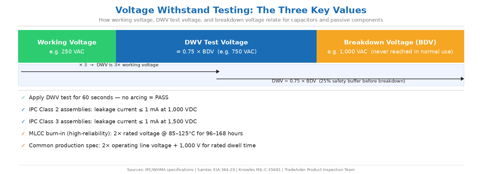
DWV test voltage, working voltage, and breakdown voltage — how the three values relate during capacitor and component voltage withstand testing.
Counterfeit Component Risk and Detection
Why Passive Components Are Frequently Counterfeited
Capacitors and resistors are among the most frequently counterfeited passive components because they are inexpensive, sourced in high volumes, and — critically — difficult to distinguish from legitimate parts through visual inspection alone. In 2022, ERAI reported a 35% increase in reported counterfeit parts compared to 2021, even as global semiconductor sales remained flat — a trend that reflects growing sophistication in counterfeiting methods rather than increased supply scarcity alone.
Counterfeit passive components typically fall into one of three categories: parts with incorrect values remarked to appear as a higher-specification grade; recycled components harvested from scrap boards and repackaged as new; and cloned parts manufactured with substandard dielectric materials that exhibit normal behavior at room temperature but fail under thermal or voltage stress. Research has documented cases of counterfeit electrolytic capacitors assembled unknowingly in power supplies for medical devices, where they failed in the field — with the counterfeiting identified only after field failure analysis.
The capacitor plague of the early 2000s remains the most documented large-scale example: millions of aluminum electrolytic capacitors with improperly formulated electrolytes were distributed through the supply chain and assembled into motherboards and power supplies by major manufacturers including Dell, HP, and IBM before the defect was identified. Dell alone spent an estimated $420 million replacing affected systems.
For buyers sourcing electronic components or assembled boards from Chinese factories, the risk profile is highest when procurement goes through brokers or non-authorized channels. Tolerance screening and DWV testing at incoming inspection provide the electrical evidence that visual inspection cannot.
Detection Steps During Incoming Inspection
A multi-layer incoming inspection protocol for passive components should combine visual examination, electrical measurement, and — for high-risk lots — non-destructive internal analysis. The sequence below reflects the AS6171 standard framework for suspect/counterfeit component detection:
Step 1 — Documentation verification: Cross-check part numbers, date codes, and country of origin markings on the reel or packaging against the purchase order and the original component manufacturer's (OCM) specifications. Discrepancies in font, logo clarity, or date code format are early indicators of remarking or re-packaging.
Step 2 — External visual inspection: Under magnification (10×–40×), inspect for evidence of sanding, blacktopping (a remarking technique that applies a thin coating over original markings), inconsistent lead finish, or package dimensions that differ from the OCM datasheet. SMD resistors and capacitors should be checked for marking consistency across the sampled lot.
Step 3 — Electrical measurement: Measure the key electrical parameter — capacitance for capacitors; resistance for resistors — against the labeled value and tolerance. Any unit that measures outside the labeled tolerance grade is an immediate reject. ESR measurement is added for electrolytic capacitors.
Step 4 — DWV test (for voltage-critical applications): Apply the specified test voltage for the component's rated voltage class per the relevant standard. Monitor leakage current for the full dwell time. Dielectric breakdown or leakage current exceeding the specified limit constitutes failure.
Step 5 — X-ray inspection (for high-risk lots): Non-destructive X-ray imaging reveals internal construction. Recycled components often show wire bond degradation, die paddle design differences from the OCM's standard construction, or incomplete dielectric fill that external inspection cannot detect.
Applying this protocol to the full incoming lot using AQL sampling — rather than spot-checking — transforms it from a reactive quality tool into a systematic gatekeeping function that protects the entire production run.
How Third-Party Inspection Supports Component Quality Control
For buyers who cannot perform electrical characterization and DWV testing in-house, third-party inspection at the factory or at a testing laboratory provides an independent verification layer before components are assembled or shipped. An independent inspector with access to calibrated LCR meters, hipot testing equipment, and X-ray capability can execute the incoming inspection protocol described above against the AQL sample size appropriate for the shipment.
This is particularly relevant when sourcing assembled electronic products from Chinese manufacturers, where passive components may be procured from the manufacturer's own supplier network rather than from authorized distributors. Bringing in third-party product testing and inspection before shipment — when any lot rejection can still be resolved at the factory — eliminates the much higher cost of dealing with field failures or regulatory non-compliance after goods arrive in market.
TradeAider's product testing services cover electrical and electronic product categories, and can be coordinated alongside pre-shipment inspection to verify both physical assembly quality and electrical component specifications in a single engagement before goods leave the factory.
Catching a batch of out-of-tolerance capacitors or a lot of resistors that fail DWV testing at the factory stage costs a fraction of what the same defect costs after assembly, shipment, and market entry. Contact TradeAider to discuss an inspection and testing plan for your next electronic product shipment.
Frequently Asked Questions
What is the difference between tolerance screening and DWV testing for capacitors?
Tolerance screening verifies that a capacitor's capacitance value falls within the labeled percentage of its nominal value — a measurement of whether the component is the correct value. DWV testing verifies that the component's dielectric insulation can withstand a voltage significantly above its rated working voltage without breaking down — a measurement of safety margin and dielectric integrity. Both tests are necessary for incoming inspection because a capacitor can have correct capacitance but a compromised dielectric (and vice versa). Tolerance screening uses an LCR meter; DWV testing uses a hipot tester applying elevated voltage and monitoring leakage current.
What test voltage should be used for DWV testing of a capacitor rated at 50V DC?
The DWV test voltage for a 50V DC rated capacitor is typically set at 2.5× to 3× the working voltage, depending on the applicable standard. For general commercial components, a common practice is to apply 125 to 150V DC for a 60-second dwell with a leakage current limit appropriate to the component class. For high-reliability MLCC burn-in under MIL specifications, the test voltage rises to twice the rated working voltage at elevated temperature (85°C or 125°C) for 96 to 168 hours. Always consult the component manufacturer's datasheet and the applicable standard (MIL-C-55681, IEC 60384, or customer specification) to confirm the correct test voltage and acceptance criteria for your application.
How do I know if resistors or capacitors received from a Chinese supplier are counterfeit?
Visual inspection alone is insufficient for detecting counterfeit passive components. The minimum reliable detection protocol combines: documentation verification (part number, date code, and lot traceability against OCM records); external visual inspection under magnification for marking consistency, package dimensions, and evidence of remarking; and electrical measurement of the key parameter (resistance or capacitance) against the labeled tolerance grade. For electrolytic capacitors, ESR measurement adds a further layer. For high-risk lots, non-destructive X-ray imaging reveals internal construction anomalies. Components that measure outside their labeled tolerance, or show internal construction inconsistent with the OCM's standard design, should be treated as suspect regardless of external appearance.
Related Articles

Grow your business with TradeAider Service
Click the button below to directly enter the TradeAider Service System. The simple steps from booking and payment to receiving reports are easy to operate.