- À Propos de Nous

- Nos Services
- Votre Industrie
- Ressources
- Actualités et Blog
Electronic components fail quietly. A capacitor with the wrong tolerance, a diode that breaks down under load, or a batch of counterfeit ICs from an unverified supplier — these failures rarely announce themselves until the product is already in a customer's hands. For importers sourcing electronics from China, that gap between factory shipment and customer delivery is where fortunes are made or lost. Understanding which testing methods exist, what they detect, and when to apply them is not a technical luxury — it's a basic requirement for protecting your brand and your margins.
This guide covers every major category of electronic component testing: what each method measures, the defects it catches, and how it fits into a practical quality control workflow for importers.
Key Takeaways
- Electronic component testing spans five main categories: visual/mechanical, electrical, safety/compliance, environmental/reliability, and advanced functional testing.
- No single test catches everything — a robust QC program layers multiple methods to cover the full defect spectrum.
- Counterfeit detection methods (X-ray, decapsulation, SAM analysis) are increasingly important for importers buying from the open market in China.
- Third-party product testing services provide the independent verification that supplier self-reporting cannot.
Why Testing Electronic Components Matters for Importers
The Real Cost of Skipping Component Testing
The electronics components market is projected to exceed $643 billion by 2027, growing at a CAGR of 6.5% (Research and Markets). That growth brings opportunity — and a proportional increase in the risk of substandard or counterfeit parts entering the supply chain. According to research published in IEEE Xplore, the key challenges in electronic components testing include difficulty accessing authentic datasheets, absence of standardized test procedures across suppliers, and the increasing sophistication of counterfeit parts that visually mimic genuine components.
For an Amazon FBA seller or a Shopify brand importing electronics from China, a single shipment of non-compliant or counterfeit components can trigger account suspensions, product recalls, and direct financial losses that far exceed any savings made on per-unit cost. Testing is not overhead — it's insurance.
How Component Defects Enter the Supply Chain
Defects enter at four main points: raw material sourcing (wrong or substandard materials), manufacturing (soldering errors, wrong values, dimensional tolerances), packaging and handling (ESD damage, moisture ingress), and distribution (counterfeit parts substituted for genuine ones in the open market). Each entry point corresponds to a specific testing category. A well-designed inspection program addresses all four.
Visual and Mechanical Inspection
Visual inspection is always the first layer of any component testing program. It's fast, requires minimal equipment, and eliminates the most obvious defects before more resource-intensive testing begins.
Standard Visual and Dimensional Inspection
A trained inspector examines components under magnification for physical damage: cracks, chips, corrosion, deformation, incomplete plating, or burn marks. For surface-mount devices, the focus is on lead coplanarity — all leads must sit flat against a reference surface within tolerance. Dimensional verification using calipers or optical comparators checks that package dimensions, pin pitch, and lead length match the manufacturer's datasheet.
Visual inspection also covers marking verification: part numbers, date codes, lot codes, and manufacturer logos must be consistent and correctly applied. Blurred, re-marked, or inconsistent markings are a primary red flag for counterfeit components.
X-Ray Non-Destructive Inspection
X-ray inspection reveals what visual inspection cannot: the internal structure of a component without destroying it. For ball grid arrays (BGAs), flip-chip packages, and other components where solder joints are hidden under the package, X-ray is the only non-destructive way to verify joint quality. It detects solder voids, bridges, open joints, and misalignment.
For counterfeit detection, X-ray is particularly powerful. It can verify the lead frame geometry, wafer dimensions, and gold wire bonding arrangement inside an IC package — characteristics that counterfeiters cannot easily replicate. Any deviation from the authentic manufacturer's internal structure is immediately visible.
Electrical Testing Methods
Electrical testing verifies that a component's measured parameters match its specified values. This is the largest and most technically varied category of component testing.
Multimeter and Continuity Testing
A digital multimeter (DMM) is the most fundamental electrical test tool. It measures voltage, current, and resistance — the three properties that define whether a passive component is operating within specification. For resistors, the measured resistance is compared against the rated value and tolerance. For diodes, forward and reverse bias behavior is checked. For capacitors, a DMM with a capacitance function measures stored charge against the rated value.
Continuity testing — a subset of DMM testing — confirms that electrical connections are intact. An audible beep or near-zero resistance reading indicates a complete circuit path. This is essential for checking solder joints, wire harnesses, PCB traces, and connector integrity.
LCR Testing (Inductance, Capacitance, Resistance)
Dedicated LCR meters measure passive component values with higher accuracy and across a range of test frequencies. Unlike a basic DMM, an LCR meter can characterize a capacitor's equivalent series resistance (ESR) — a critical parameter for power supply filtering that a basic capacitance reading won't reveal. High ESR in an electrolytic capacitor indicates aging or poor quality, even if the capacitance value appears correct.
Impedance analysis — a related technique — measures a component's total resistance to alternating current at specified frequencies. This is especially important for RF components, inductors, and filter networks where frequency-dependent behavior is a core part of the specification.
In-Circuit Testing (ICT) and Automated Test Equipment (ATE)
In-Circuit Testing (ICT) tests components on an assembled PCB by connecting test probes directly to specific nodes in the circuit while the board is powered. Using a bed-of-nails fixture — a custom array of spring-loaded probes — ICT can verify individual component values, check for solder shorts and opens, and confirm correct component orientation, all without requiring the board to run through its full operating routine. It's most effective in high-volume manufacturing environments where the same PCB design is tested repeatedly.
Automated Test Equipment (ATE) extends this concept to a computer-controlled platform capable of running hundreds or thousands of parametric tests per second. ATE systems can perform functional tests, parametric sweeps, and boundary-scan tests (JTAG) on complex digital and mixed-signal assemblies. For high-volume production runs, ATE dramatically reduces testing time and eliminates the human variability inherent in manual testing.
| Testing Method | Primary Use | Best For | Defects Caught |
|---|---|---|---|
| Visual Inspection | Physical damage, markings | All components | Cracks, re-marking, corrosion |
| X-Ray Inspection | Internal structure | BGAs, ICs, counterfeit detection | Solder voids, fake die, wire bond issues |
| Multimeter / LCR | Parametric values | Passives, diodes, transistors | Out-of-spec values, open/short circuits |
| ICT / ATE | Board-level verification | Assembled PCBs, high-volume runs | Wrong values, orientation errors, solder defects |
| ESD Testing | Electrostatic discharge tolerance | Semiconductors, ICs | Latent ESD damage, substandard packaging |
| Environmental Testing | Stress and reliability | All components in demanding applications | Early failures, moisture sensitivity, vibration failure |
Safety and Compliance Testing
Safety testing verifies that components meet both international standards and destination-market regulations. For importers, this is the category most directly tied to compliance, liability, and market access.
ESD Anti-Static Testing
Electrostatic discharge (ESD) is one of the leading causes of latent IC failure — damage that doesn't cause immediate failure but dramatically shortens component life. ESD testing measures a component's sensitivity to electrostatic discharge using standardized models: the Human Body Model (HBM), Machine Model (MM), and Charged Device Model (CDM). Components are classified by their withstand voltage; those falling below specification are either defective or counterfeit.
For importers receiving ICs and other semiconductors from Chinese suppliers, ESD-related failure is a specific risk when packaging, handling, and transport conditions are not controlled. Components that survived factory testing may arrive with ESD-induced latent damage — appearing functional on initial inspection but failing prematurely in use.
Solderability Testing
Solderability testing evaluates whether a component's leads or terminations can form reliable solder joints. The primary standard is IPC J-STD-002, which specifies test conditions for solderability of component leads, terminations, and wires. A component with poor solderability will form cold joints or no joints at all during PCB assembly, leading to intermittent connections or outright failures in the field.
Solderability degrades over time through oxidation and contamination of lead finishes. Components that have been stored improperly, refurbished from used PCBs, or have exceeded their shelf life will often fail solderability testing. This is a particularly relevant test for components sourced through independent distributors or gray-market channels.
RoHS Compliance via XRF Analysis
X-ray Fluorescence (XRF) analysis is a non-destructive technique that determines the elemental composition of a component's materials. For electronics exporters and importers serving the EU, UK, US, Australia, and Canada, RoHS (Restriction of Hazardous Substances) compliance is a legal requirement, restricting the use of lead, mercury, cadmium, hexavalent chromium, and specific flame retardants.
XRF analysis can detect lead in solder finishes — a common issue with components manufactured before the global lead-free transition — as well as other restricted substances in plating materials and housing compounds. Failure to screen for RoHS compliance before export can result in shipment rejection, customs penalties, and destruction of the entire consignment at the importer's expense.
Environmental and Reliability Testing
Environmental testing subjects components to the physical conditions they will encounter during their operational life — often in accelerated form to predict long-term performance in a shorter timeframe. This category is essential for components destined for demanding applications.
Temperature and Humidity Testing
Temperature cycling tests expose components to repeated transitions between high and low temperature extremes, simulating the thermal stresses of normal power cycling. The coefficient of thermal expansion (CTE) mismatch between different materials in a component — die, lead frame, encapsulant — generates mechanical stress with each cycle. Components that fail temperature cycling will exhibit solder joint cracking, delamination, or wire bond fatigue.
Humidity testing (damp heat testing, per IEC 60068-2-78) evaluates resistance to moisture ingress and corrosion. High humidity accelerates corrosion on lead finishes and can cause moisture-induced cracking in plastic-encapsulated components when they are subsequently soldered at reflow temperatures — a failure mode known as "popcorning."
Vibration and Shock Testing
Vibration testing subjects components to controlled sinusoidal or random vibration profiles to simulate the mechanical environment of their end application — automotive, industrial machinery, transportation, or consumer products. Shock testing applies high-magnitude, short-duration impulses to simulate drop events and impact loading.
Both tests are defined by standards including MIL-STD-202, IEC 60068-2-6 (vibration), and IEC 60068-2-27 (shock). Components that fail these tests exhibit broken leads, cracked packages, or detached die attachments. For a Shopify brand selling portable electronic products, shock and vibration resistance directly determines product durability and return rates.
High-Temperature Ageing (Burn-in Testing)
Burn-in testing operates components at elevated temperature — typically 125°C — under electrical stress for an extended period to accelerate the failure of components that would fail early in normal use. This deliberately triggers failures caused by latent manufacturing defects, filtering them out before the product ships.
The technique exploits the bathtub curve of component reliability: a well-known model where failure rate is highest at the very beginning of life ("infant mortality"), drops to a low steady-state value during useful life, and rises again near end of life. Burn-in eliminates the infant mortality region, delivering only components with lower early-life failure rates to the customer.
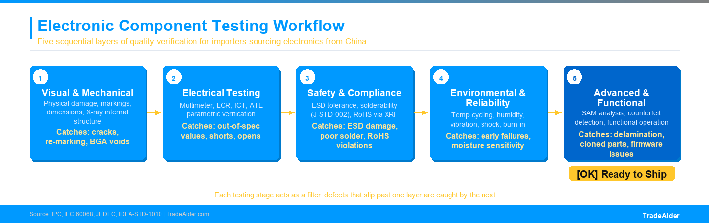
Each testing stage acts as a filter: defects that pass one layer are caught by the next. Skipping stages creates gaps that reach the end customer.
Advanced and Specialized Testing Methods
Beyond standard parametric and environmental testing, a set of specialized methods addresses the most difficult failure modes — ones that are invisible to standard electrical tests and that primarily emerge in complex assemblies or when counterfeit parts are suspected.
Functional Testing
Functional testing verifies that a component or assembly performs its intended function under simulated operating conditions — not just that its individual parameters are within specification. An IC that passes all parametric tests may still fail to execute its programmed function correctly if its firmware has been altered, its process corners are marginal, or its internal architecture doesn't match the genuine part.
For importers buying finished electronic products from Chinese suppliers, functional testing at the system level — pressing buttons, running through all operating modes, confirming all inputs and outputs respond correctly — is the most practical and accessible form of functional verification available without specialized equipment.
SAM (Scanning Acoustic Microscopy) Failure Analysis
Scanning Acoustic Microscopy (SAM) uses ultrasonic waves to image the internal structure of electronic packages without opening them. Unlike X-ray, which shows density variations, SAM detects interface delamination, cracks, voids, and moisture pockets — failure modes that are transparent to X-ray but highly reflective to ultrasound.
SAM is particularly valuable for detecting delamination between the die attach material and the package substrate — a failure mode that becomes catastrophic during reflow soldering as moisture-induced pressure causes the package to crack. It is also used in failure analysis to locate the root cause of field failures before destructive analysis is performed.
Counterfeit Detection Techniques
Counterfeit electronic components are a material risk for importers sourcing from the open market in China. Counterfeit parts fall into several categories: remarked parts (genuine but lower-grade parts with upgraded markings), recycled parts (harvested from used PCBs and resold as new), cloned parts (non-genuine die in a copied package), and overproduced parts (genuine die, but manufactured outside the official production run and released through unauthorized channels).
Each counterfeit type requires different detection methods. Remarked parts are caught by chemical decapsulation — removing the plastic package to expose the die marking and compare it against authentic samples. Recycled parts often show solder residue on their leads, visible under magnification. Cloned parts require X-ray and decapsulation to compare internal die geometry and process characteristics. Overproduced parts may be indistinguishable without lot traceability documentation from the original manufacturer.
The IDEA-STD-1010 standard (published by ERAI, the Electronic Resellers Association International) provides a comprehensive framework for counterfeit component testing and reporting. Importers working with independent distributors should require suppliers to demonstrate compliance with this standard or an equivalent, such as AS6081 for aerospace applications.
Choosing a Third-Party Testing Partner for Your Electronics Order
For most importers, the practical question is not which tests to perform in-house — it's which testing methods to specify when commissioning a professional product testing service. A credible third-party testing partner should be able to clearly explain which tests are appropriate for your specific component type and application, provide test reports with actual measured values (not just pass/fail stamps), and reference the specific standards their tests are conducted against.
The most important questions to ask a testing provider:
- Which standards govern your test procedures? (IPC, IEC, MIL-STD, JEDEC?)
- Is your facility accredited for the tests you perform, and by which accreditation body?
- Can you provide sample test reports from previous projects?
- Do you perform counterfeit detection testing, and which methods do you use?
- What is your report turnaround time, and is real-time access to results available?
TradeAider's product testing service connects importers with certified testing facilities for hardline, softline, and electrical/electronic products, with transparent pricing and real-time visibility into test progress. For importers who need to verify compliance before goods ship from China, this removes the uncertainty of relying solely on supplier-provided test certificates. Contact our team to discuss the right testing scope for your next electronics order.
Frequently Asked Questions
What is the most important test for detecting counterfeit electronic components?
No single test catches all counterfeit types, but the combination of visual inspection (including marking verification), X-ray analysis, and chemical decapsulation covers the vast majority of counterfeit scenarios. X-ray reveals internal structure anomalies without destroying the part; decapsulation exposes the die directly for comparison with authentic samples. For high-value or high-risk components, all three should be applied together rather than individually.
Do I need to test every component in a batch, or is sampling sufficient?
For most standard testing (parametric, environmental, solderability), AQL-based sampling is both practical and statistically defensible — testing 100% of a large batch is not feasible without automated equipment. The appropriate sample size depends on the batch quantity, the AQL level you select, and the consequence of a defect passing through. For safety-critical components or when working with an unproven supplier, use a tighter AQL (1.0 or lower) and apply testing to multiple stages: incoming inspection, during production, and pre-shipment. The AQL calculator is a useful tool for determining the right sample size for your batch.
What standards govern electronic component testing for export to the US, EU, and Australia?
Regulatory requirements vary by product category and destination market. For the EU, the key frameworks are RoHS (2011/65/EU), CE marking (covering LVD, EMC, and RED directives depending on product type), and REACH (chemical compliance). For the US, FCC authorization is required for devices that emit radio frequency energy; UL certification, while voluntary, is required by most major retailers. Australia requires RCM marking for electrical products. In all cases, testing to the relevant IEC or ANSI standard is the foundation for compliance claims. For importers unsure which requirements apply to their specific product, reviewing the inspection standards reference is a good starting point.
How does third-party product testing differ from a factory's own quality certificate?
A factory quality certificate is a self-assessment — the supplier is confirming that their own production meets their own criteria. Third-party testing is conducted by an independent organization with no commercial interest in the result. The independence is precisely the point: third-party test results can be used to verify compliance claims, support warranty and liability protection, and satisfy retailer or regulatory requirements that explicitly require independent verification. For importers, particularly those selling on Amazon FBA or into retail chains with compliance audit requirements, supplier test certificates alone are generally not sufficient.
Articles Connexes

Développez votre entreprise avec le Service TradeAider
Cliquez sur le bouton ci-dessous pour accéder directement au Système de Service TradeAider. Les étapes simples de la réservation et du paiement à la réception des rapports sont faciles à utiliser.