- À Propos de Nous

- Nos Services
- Votre Industrie
- Ressources
- Actualités et Blog
A transformer that meets its rated specifications at room temperature with no load is not the same transformer that will perform reliably after six months of continuous operation in a 45°C ambient environment. Electronic transformers — the toroidal, EI-core, and planar designs used in power supplies, switching converters, industrial controls, and consumer electronics — are among the components most susceptible to quality failures that are invisible at incoming visual inspection. Their failure modes are thermal and dielectric: insulation that degrades over time from heat, or that breaks down suddenly when subjected to voltage transients above the rated level. For buyers sourcing electronic assemblies or standalone transformer components from Chinese manufacturers, knowing which tests to require and how to read the results is the difference between a product that operates within its rated service life and one that fails in the field.
Key Takeaways
- Three tests — inductance measurement, dielectric withstand (hi-pot), and temperature rise under full load — together verify that an electronic transformer will perform reliably across its rated operating conditions.
- Hot-spot temperature, not average winding temperature, is the limiting factor for transformer insulation life; buyers should specify and verify the hot-spot limit against the transformer's insulation class.
- IEC 60076 and IEC 60076-11 define the standard testing requirements for power and dry-type transformers; buyers should require manufacturer test reports referencing these standards for any transformer intended for regulated market entry.
Why Electronic Transformer Testing Matters at the Procurement Stage
Types of Electronic Transformers and Their Applications
Electronic transformers span a wide range of designs and applications, but from a quality inspection perspective, they share a common set of failure modes: insulation breakdown from voltage stress, thermal degradation from excessive heat, and impedance or inductance drift from improper core material, air-gap, or winding construction. The relevant transformer types include:
Switch-mode power supply (SMPS) transformers (EE, EI, planar core designs): Used in AC adapters, server power supplies, industrial converters. High-frequency operation (20 kHz to several hundred kHz) makes them sensitive to core loss, leakage inductance, and winding capacitance.
Line-frequency isolation transformers (EI laminated core, toroidal): Used for galvanic isolation, noise filtering, and voltage conversion at 50–60 Hz. Insulation integrity between primary and secondary is the dominant safety parameter.
Current transformers (CTs) and measurement transformers: Used in metering and protection circuits. Accuracy and linearity over the measurement range are critical quality parameters.
The testing approach described in this article focuses primarily on line-frequency and low-frequency switching transformers, which are the most common types encountered in product inspection for consumer electronics, industrial equipment, and power supply assemblies sourced from China.
Inductance Testing
What Inductance Measurements Tell You
An LCR meter or impedance analyzer measures the key inductive parameters of a transformer at specified frequency and test signal levels. The two primary parameters are magnetizing inductance and leakage inductance, and each reveals a different aspect of the transformer's construction and performance.
Magnetizing inductance (L_m) is measured at the primary winding with the secondary open-circuit. It reflects the core material properties, the number of primary turns, and the cross-sectional area of the core. Low magnetizing inductance compared to specification indicates a core material substitution (typically a lower-permeability grade), fewer turns than specified, or an air gap that was not present in the original design. In a power supply transformer, low magnetizing inductance increases no-load current draw and core losses, reducing efficiency and increasing operating temperature.
Leakage inductance (L_k) is measured at the primary with the secondary short-circuited. It reflects the quality of winding coupling — how effectively the primary and secondary magnetic fluxes are linked. High leakage inductance compared to specification indicates poor winding geometry, insufficient interleaving of primary and secondary layers, or incorrect bobbin construction. In switching converters, excessive leakage inductance causes voltage spikes on the switching node that can exceed transistor voltage ratings and generate EMI.
DC resistance (DCR) of both primary and secondary windings — measured with a milliohmmeter or four-wire resistance measurement — provides direct evidence of wire gauge compliance. A winding with fewer turns or thinner wire than specified will show lower resistance than specified (fewer turns) or higher resistance (thinner wire). Cross-checking DCR against the turns ratio and nominal wire gauge catches winding substitutions that inductance measurement alone might miss.
Leakage Inductance and Magnetizing Inductance: Measurement Conditions
Inductance measurements on transformers are frequency-dependent and level-dependent. For accurate results, measurements should be made at the frequencies and signal levels specified in the manufacturer's test specification or, where not specified, at the frequencies relevant to the application:
Line-frequency (50/60 Hz) transformers: measure at 50 or 60 Hz with a test signal level low enough to avoid core saturation (typically 1 Vrms or below for LCR bridge measurement). The ratio of open-circuit to short-circuit inductance — magnetizing inductance to leakage inductance — should typically be at least 100:1 for well-coupled transformer designs, and is specified per design by the manufacturer.
SMPS transformers: measure at the operating frequency of the converter design. Core materials optimized for high-frequency operation (ferrite, powdered iron) have sharply different permeability characteristics at 50 Hz versus 100 kHz — a line-frequency measurement of an SMPS transformer yields misleading results and should not be used as a quality criterion without frequency normalization.
Inductance and Electrical Test Summary for Electronic Transformers
| Test | Configuration | What It Reveals | Typical Instrument | IEC Reference |
|---|---|---|---|---|
| Magnetizing Inductance (L_m) | Primary open, secondary open | Core material, turn count, air gap | LCR meter / impedance analyzer | IEC 60076-1 |
| Leakage Inductance (L_k) | Primary energized, secondary short-circuited | Winding coupling quality | LCR meter / impedance analyzer | IEC 60076-1 |
| DC Winding Resistance (DCR) | Per winding, 4-wire measurement | Wire gauge, turn count compliance | Milliohmmeter / 4-wire meter | IEC 60076-1 |
| Turns Ratio | Primary vs. secondary open-circuit voltage | Output voltage compliance, winding integrity | Turns ratio meter / voltage measurement | IEC 60076-1 |
| Dielectric Withstand (Hi-Pot) | Primary to secondary, primary to earth | Insulation integrity under voltage stress | Hi-pot tester (AC or DC) | IEC 60076-3 |
| Temperature Rise Under Load | Full rated load, equilibrium temperature | Thermal adequacy of design and cooling | RTD / thermocouple + resistance method | IEC 60076-2 / IEC 60076-11 |
Dielectric Strength Testing for Transformers
Applied Voltage Test (Hi-Pot)
The applied voltage test — commonly called the hi-pot test or dielectric withstand test — applies a voltage significantly higher than the transformer's rated operating voltage between electrically isolated portions: primary to secondary, primary to earth (core/frame), and secondary to earth. IEC 60076-3 defines insulation levels and dielectric testing requirements for different transformer voltage classes. The test voltage is typically applied for 60 seconds at power frequency (50 or 60 Hz), with no breakdown and no leakage current exceeding the specified limit as the pass criterion.
For low-voltage electronic transformers with primary voltage up to 1 kV, the applied test voltage between primary and secondary windings is typically 2 kV AC (or the equivalent DC value) for one minute. Safety agency certifications (UL, CE, TUV) specify the exact test voltage based on the rated working voltage class and the required isolation level (basic insulation, reinforced insulation, double insulation). A transformer intended for a mains-connected product must demonstrate reinforced insulation, which requires a higher test voltage than basic insulation alone.
The test reveals insulation failures from: insufficient winding-to-winding clearance; inadequate creepage distances on the bobbin; contamination of the insulation barrier with conductive material; and degraded insulation tape that has cracked or delaminated during winding. All of these are manufacturing defects that can be introduced during production and that visual inspection cannot detect.
Induced Voltage Test
The induced voltage test applies twice the rated voltage to the primary winding for a specified duration (typically 5 seconds at twice frequency, or 60 seconds at rated frequency) to verify the inter-turn and inter-layer insulation integrity within each winding. Unlike the applied voltage test which checks isolation between windings, the induced voltage test verifies the insulation between turns and layers within a single winding — a failure mode that the applied voltage test does not cover.
For small electronic transformers, the induced voltage test is performed on the primary winding at twice the rated voltage (at twice the rated frequency to prevent core saturation). The test time at double frequency is proportional to the ratio: a 60-second test at rated frequency is equivalent to a 30-second test at twice the frequency. Any turn-to-turn short will cause excessive current draw and a measurable rise in primary input current, which is the failure indicator.
Partial Discharge (PD) Measurement
For higher-voltage transformers and those intended for demanding applications, partial discharge measurement provides a more sensitive indicator of insulation defects than hi-pot testing alone. Partial discharges are small localized electrical breakdowns within the insulation or at the insulation surface that do not immediately constitute a complete dielectric failure but indicate insulation degradation that will progress over time. IEC 60076-1 and IEEE C57.12.90 classify partial discharge testing as a special test — not mandatory for every unit but typically required in procurement contracts for critical applications and high-voltage designs.
Temperature Rise Testing Under Load
Why Hot-Spot Temperature Is the Critical Value
Temperature rise testing applies the rated current to the transformer windings and holds it until thermal equilibrium is reached — the point at which heat generated by winding losses and core losses equals heat dissipated to the environment. The temperature rise measurement is the difference between the average winding temperature at equilibrium and the ambient temperature during the test.
The limitation of average winding temperature as a metric is that it does not capture the hottest point in the winding. The hottest-spot temperature is the sum of ambient temperature, measured temperature rise, and a hot-spot allowance above the average winding rise — typically 10°C above average for oil-immersed transformers and 15–30°C for dry-type transformers, depending on design. It is this hot-spot temperature that determines the rate of insulation aging and the transformer's service life, because the cellulose paper or polymer insulation at the hot spot experiences the highest thermal stress.
The relationship between hot-spot temperature and insulation life follows the Arrhenius equation — a principle established in transformer loading guides — which predicts that insulation life halves for approximately every 6–8°C increase above the rated hot-spot limit. A transformer operating 10°C above its rated hot-spot temperature will age at approximately twice the normal rate, halving its expected service life without any visible indication during inspection.
Insulation Class and Temperature Rise Limits
Transformer insulation systems are classified by their maximum allowable temperature, and each class has a corresponding standard temperature rise rating. The insulation class to standard temperature rise relationships are: Class 220 system (former "H") — 150°C rise; Class 180 (former "F") — 115°C rise; Class 150 (former "B") — 80°C rise; Class 105 (former "A") — 50°C rise. These ratings assume a maximum ambient temperature of 40°C. A transformer's actual hot-spot temperature equals ambient + temperature rise + hot-spot allowance.
For dry-type transformers, the three standard temperature rise options are 80°C, 115°C, and 150°C rise, all based on a maximum ambient temperature of 40°C. A dry-type transformer with an 80°C rise will operate at an average winding temperature of 120°C (40+80) when fully loaded at maximum ambient. Since the insulation used in most dry transformers is rated at 220°C, the 80°C rise unit provides the widest thermal margin and the longest insulation life at full load — but comes at higher material cost due to the larger core and winding design required.
For oil-immersed transformers, IEEE C57.12.00 and IEC 60076 specify temperature rise limits of 65°C for average winding rise and 80°C for hot-spot rise above ambient. Loading capability decreases approximately 1% per degree Celsius of ambient temperature increase above the 30°C rating basis.
What to Require from Your Supplier
For electronic transformers sourced from Chinese manufacturers, buyers should specify the following in the purchase order and require corresponding test reports before shipment:
Factory Acceptance Test (FAT) report documenting: turns ratio measurement results; winding resistance (DCR) per winding; no-load current at rated primary voltage; dielectric withstand test results (applied voltage value, duration, and leakage current); temperature rise test result — both average winding temperature rise and estimated or measured hot-spot temperature.
Insulation class declaration confirming the specific insulation system class (Class 105, 150, 180, or 220) and its compliance with the applicable standard — IEC 60076-11 for dry-type transformers, IEC 60076-2 for liquid-immersed transformers.
Safety certification reference where applicable: CE marking to Low Voltage Directive 2014/35/EU for EU market entry; UL 5085 series for North American market. Safety certification test reports from accredited bodies provide third-party verification that dielectric and temperature rise requirements have been met on the type unit.
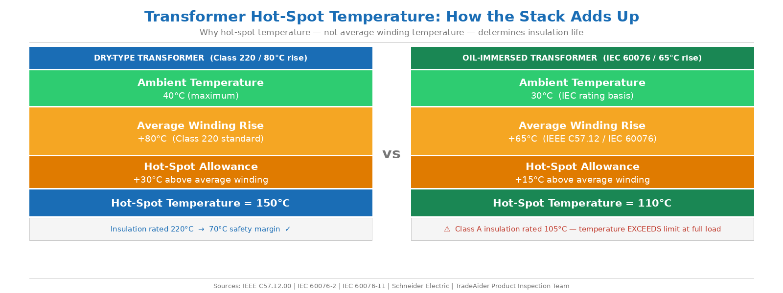
How hot-spot temperature is calculated from ambient temperature, rated temperature rise, and hot-spot allowance — for dry-type and oil-immersed transformers.
How to Read a Factory Test Report for Transformers
A complete transformer factory test report from a competent manufacturer should contain measured values for all routine tests per the applicable standard, with the acceptance limits and actual measured results clearly stated. When reviewing a test report for an electronic transformer received from a Chinese supplier, check the following systematically:
Turns ratio: The measured ratio should match the nameplate specification within the tolerance stated by the manufacturer (typically ±0.5% for distribution transformers). A ratio outside tolerance indicates a winding error — excess or insufficient turns on one winding.
Winding resistance: The measured DCR per winding should be close to the calculated theoretical value based on wire gauge and turn count. Significant deviation (more than ±5%) in either direction warrants a wire gauge verification request.
No-load current and losses: The no-load current at rated primary voltage reflects core material quality and core loss. High no-load current relative to specification indicates lower-permeability core material, additional air gaps, or an undersized core cross-section. IEEE allows a tolerance of up to 10% for specified no-load losses and up to 6% for total losses on new transformers.
Dielectric test result: The report should state the test voltage applied, the test duration, and either the measured leakage current or a pass/fail statement. A report that states only "passed" without the test voltage value and duration is incomplete — request a revised report with the specific values.
Temperature rise result: The report should state the measured average winding temperature rise (in °C) and the ambient temperature during the test. From these, you can calculate the estimated hot-spot temperature using the hot-spot allowance for the insulation class and compare it against the rated insulation class maximum.
Requesting test reports before shipment, verifying the measured values against the agreed specification, and conducting spot-check incoming verification testing against the most critical parameters — turns ratio, winding resistance, and hi-pot — constitutes a proportionate quality assurance approach for electronic transformer procurement.
TradeAider's product testing services for electrical and electronic products include verification of transformer electrical parameters and dielectric safety testing, coordinated with pre-shipment inspection for assembly quality. For buyers qualifying a new transformer supplier, a factory audit can verify whether the supplier's production and testing capabilities are adequate to consistently produce transformers that meet the specified electrical and thermal requirements. Contact TradeAider to discuss a testing and inspection plan for your transformer procurement from China.
Frequently Asked Questions
What is the difference between dielectric withstand (hi-pot) testing and induced voltage testing for transformers?
The dielectric withstand (hi-pot or applied voltage) test applies a high voltage between isolated portions of the transformer — primarily primary to secondary and primary to earth — to verify that the insulation barrier between them can withstand voltage stress without breakdown. It tests isolation integrity. The induced voltage test applies twice the rated voltage to one winding to verify the inter-turn and inter-layer insulation within each individual winding. These two tests are complementary: hi-pot finds insulation failures between windings; induced voltage test finds turn-to-turn shorts within a winding. A transformer may pass one and fail the other — both tests are needed for a complete dielectric safety verification.
What insulation class should I specify for a transformer rated for continuous operation in a 45°C ambient environment?
Operating temperature must be calculated from the full stack: ambient + temperature rise + hot-spot allowance. In a 45°C ambient, the effective maximum allowable average winding rise is reduced by 5°C compared to the standard 40°C reference. For a transformer with a Class 180 insulation system (standard 115°C rise), the effective average rise available is 110°C (115 – 5), giving an estimated hot-spot temperature of 45 + 110 + 15 = 170°C against the 180°C insulation limit — a 10°C margin. For continuous operation with reliability headroom, specifying a Class 220 insulation system (rated for 150°C rise) provides substantially more thermal margin in elevated ambient conditions and extends insulation service life. Consult the transformer manufacturer's datasheet for the specific hot-spot allowance applicable to their design.
What routine tests should be documented in a factory test report for electronic transformers?
Per IEC 60076-1 and IEC 60076-11 (for dry-type transformers), routine tests that should be documented in the factory test report include: winding resistance measurement (DCR per winding); turns ratio and polarity; impedance voltage and load loss at rated current; no-load loss and no-load current at rated voltage; and dielectric routine tests (applied voltage test between windings and between windings and earth). Temperature rise testing is classified as a type test in IEC 60076 — conducted on prototype units to validate the design, not necessarily on every production unit. For production lots, buyers can request type test reports from the manufacturer demonstrating that the design has been type-tested for temperature rise, and rely on routine test reports for individual unit verification.
Articles Connexes


Développez votre entreprise avec le Service TradeAider
Cliquez sur le bouton ci-dessous pour accéder directement au Système de Service TradeAider. Les étapes simples de la réservation et du paiement à la réception des rapports sont faciles à utiliser.