
For a power strip or extension cord order, buyers need more than a power-on result. The inspection must cover the actual plug system, cord variant, socket construction and protective features being supplied. A working lamp can coexist with an incorrect connection, and a mark on one component does not establish that the complete assembly has the required safety evidence.
This power strip and extension cord inspection checklist covers grounding, polarity, strain relief, socket fit, cord markings and overload evidence. It helps procurement and quality teams agree what finished-goods checks can establish, what reports must cover, and what needs specialist evaluation. Electrical work requires qualified personnel, suitable equipment and the adopted procedures; the checklist is not a substitute for a complete safety assessment.
A Six-Point Inspection Checklist
Before using the list, identify whether the product is a power strip, an extension cord, a reel or an assembly with additional functions, and which market requirements apply. The category and construction determine which rows are applicable; they do not all inherit one generic certificate.
Use the six checks to agree scope for each model and cord variant. Require results by applicable outlet or connector, not one aggregate electrical pass. Mechanical, continuity and polarity work must be done on disconnected units, with specialist energized testing separately planned through qualified personnel and suitable equipment.
- Grounding: For a grounded design, check the path from the plug earth contact to every required outlet earth contact and accessible metal part. Record measured resistance, test conditions and the applicable limit; a meter beep alone is insufficient.
- Polarity: Compare the actual conductor connections with the approved circuit and plug system. Check every outlet, including relevant switch positions, and identify crossed, missing or intermittent connections.
- Strain relief: Inspect cable anchorage at the plug, connector and strip housing. Apply only the specified pull, twist or flex procedure, record movement or damage, and repeat the required connection checks afterward.
- Socket fit: Use the correct reference plugs or gauges on unpowered samples. Check insertion, seating, withdrawal and any shutters against the adopted requirements; record the outlet position of each fault.
- Cord markings: Match the cable designation, conductor count and size, length, ratings and use category to the purchase specification and approved construction. Check the finished product's identity and certification claims separately from the cable's markings.
- Overload evidence: Confirm that the relevant safety evaluation covers the complete assembly and its protective components. Compare the report's construction, loading conditions and results with the supplied version; do not infer protection from a switch or reset button.
Alongside these checks, count outlets and accessories, inspect cracked housings and sharp edges, and verify labels, instructions and carton quantities. Mark each item with the sample number, method or reference, result and disposition. If a required fixture, criterion or report is unavailable, record the check as unperformed or unresolved. That distinction prevents a blank result from becoming an assumed pass.
Make the Product Category and Destination Requirements Explicit
A power strip and an extension cord may share a flexible cable and plug, but their safety evaluations are not automatically interchangeable. Establish the product category, plug-and-socket system, rated voltage and current, indoor or outdoor claim, and whether the design includes grounding, switches, surge protection or electronic charging outputs.
UL identifies the basic US standard for relocatable power taps, commonly called power strips, as UL 1363. Its description concerns movable indoor units; an incorporated surge protective device also involves UL 1449. This helps distinguish product functions and evaluation categories. It does not make those standards universal requirements for every destination market.
For US general-use extension cords within its defined fitting scope, CPSC's extension-cord rule identifies minimum wire size, strain relief, polarization and continuity, plus outlet covers for the specified indoor two-wire polarized parallel cords and jacketing for outdoor cords. Power strips are excluded from that rule's extension-cord definition. The incorporated UL 817 reference is the 11th edition, revised through February 3, 2014; confirm the applicable legal and certification basis rather than substituting a newer edition by name.
Translate this into a short product-specific inspection plan. A two-wire cord intended for an approved two-wire application has no protective-earth conductor to measure. A grounded strip must preserve its required earth connections. Neither should be judged against the other's circuit. Obtain the actual wiring diagram and controlled construction details for each variant, especially when one retail range contains different cord lengths or plug configurations.
Require Earth-Path Coverage for Every Applicable Outlet
Protective earth, or PE, is the required protective connection to earth in an earthed design; it is distinct from neutral, the normal return conductor in the relevant supply system. Ask for the complete path from the plug earth contact to every applicable socket or connector. A passing result on one outlet does not establish coverage for the others.
Read the earth-path result for its endpoints, measured resistance and adopted method. A continuity check identifies a conductive path; a protective-earth resistance test assesses it under defined conditions and a specified limit. A meter's audible signal is not equivalent: its threshold, current and contacts may differ. The testing party must apply any lead compensation the procedure requires.
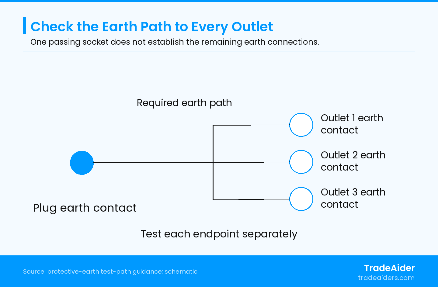
Conceptual protective-earth test map, not a physical pin layout. On the disconnected assembly, measure each required outlet earth path using the adopted method. Line and neutral are omitted; the drawing specifies no resistance limit.
The report should identify each applicable earth contact clearly enough for the buyer to see the coverage. An intact plug pin does not rule out a missing connection to one socket. Numbering the outlets and retaining the measured endpoints makes a local failure distinguishable from a whole-product label claim.
Where the plan requires testing after cable or housing stress, keep the before-and-after readings for the same endpoints. A changed or intermittent result warrants investigation even when the initial reading met the limit. Confirm fixture contact before attributing the change to the product, and keep the affected unit available for controlled examination. This is more useful than reporting a single aggregate “grounding OK” result.
Judge Polarity Against the Actual Plug System
Polarity inspection verifies that line, neutral and protective earth reach their intended terminals in a polarized system. Line is the supply conductor designated to carry the live potential; neutral and earth serve different functions. Use the model's approved connection diagram and suitably rated test equipment to trace the unpowered assembly, checking all outlets rather than only the first one.
For a specific US straight-blade example, Leviton's plug and connector instructions identify black hot wire to a brass terminal, white neutral to silver, and green ground to green for the covered grounding connector. These are instructions for that product and wiring system. Do not apply its wire colors or terminal arrangement to all international cords.
Inspect the connection, not just the insulation color. On an authorized factory examination sample, loose strands, incomplete terminal capture or an incorrect connection may require close inspection that an external function check cannot provide. Opening sealed goods should be controlled and agreed in advance; it is not a reason to dismantle every saleable unit. Record the actual finding and construction revision.
Switches complicate interpretation. An open line path may be intentional with a switch off, so compare each required switch position with the circuit rather than calling every open path a defect. For systems using reversible plugs, do not impose a fixed line-neutral orientation that the plug system does not provide. Also distinguish correct conductor routing from insulation resistance or dielectric strength: those evaluate insulation performance and require their own suitable safety-test procedures.
A Cord Boot Does Not Establish Anchorage
Strain relief prevents cord forces from reaching internal electrical connections. A molded boot may reduce bending at the entry without providing the required internal anchorage. Require construction confirmation and the specified stress result for the finished assembly, including the relevant electrical rechecks afterward.
The same Leviton instructions explain that the cord clamp relieves strain on wiring terminals and requires the covered connector's cord to be gripped securely. The practical inspection question is whether the actual anchorage performs its intended job. A smooth external entry does not answer it.
For a cord-entry failure, request the original position, defined stress condition and resulting movement or damage. The relevant electrical checks need repeating after the prescribed sequence. Do not accept a repaired demonstration without evidence that the affected production construction was corrected.
Repeat the required continuity and polarity checks after mechanical stress, following the defined sequence. If connections become intermittent, inspect the anchorage and terminations on an authorized sample rather than simply tightening the terminals and taking a new pass reading. Any repair changes the condition being assessed. Preserve the original observation, identify the correction and evaluate corrected production separately.
Separate Plug Fit from Electrical Performance
For socket fit, require the correct reference plug or gauge and configuration, together with full seating, retention and any measured-force result required by the method. A casual plug-in demonstration cannot establish insertion or withdrawal limits, and a different plug system is not a valid comparison.
The public scope of IEC 60884-2-7:2025 covers household and similar cord extension sets with or without earthing, within its stated voltage and current limits. It excludes sets with means for reeling. This is a category reference, not a universal plug-fitting tolerance or proof that a factory sample complies. Use the adopted standard and product-specific method for dimensions and forces.
Keep ordinary seating observations distinct from force measurements. A measured result needs the prescribed plug or gauge, insertion condition, force direction and rate. Repeatedly inserting an arbitrary factory plug cannot establish the same requirement.
A socket can pass a low-current continuity check while having inadequate contact pressure under service conditions. That is why connection tracing, mechanical fit and loaded temperature evaluation answer different questions. If the supplier advertises compatibility with several plug families, obtain the approved compatibility list and assess those configurations explicitly. A plug that can be pushed into a hole does not establish suitable electrical contact or protective-earth connection.
Verify the Cord and the Complete Assembly Separately
Match the delivered cable's designation, conductor count and size, voltage rating, intended use and cord length with the order and supporting construction. Keep cord markings separate from the rating and identification of the finished power strip or cord assembly. A plausible jacket legend does not resolve an undocumented material substitution.
UL's wire and cable guide distinguishes informational surface markings from the complete Listing Mark used to identify UL Listed wire or cable, which may appear on a tag, reel or smallest container. Consequently, cable printing alone is insufficient to establish the stated UL certification status. Check the appropriate identification and certification record, then separately verify any claim made for the completed power strip or cord set.
Printed conductor size also needs to agree with the controlled material specification and supporting examination or test results. Do not assume the actual conductor area or material from jacket thickness. Where construction verification requires opening or destructive measurement, agree dedicated samples and a competent method. Keep the identity of the cable manufacturer and relevant material records tied to the supplied cord variant.
For a power strip, distinguish the total assembly rating from any individual socket rating or USB output claim. A larger number printed on one component does not increase the approved rating of the assembled product. Where cord reels or outdoor versions are ordered, check the specific instructions and use limitations for those versions instead of copying the indoor straight-cord checklist unchanged.
Does the Overload Evidence Cover This Construction?
Overload evidence should show how the complete assembly behaves under its specified excessive-current or abnormal conditions. Ask which model and protective components were evaluated. A power-on check, ordinary switch operation or visible fuse cannot establish that response; specialist testing needs the applicable complete method and facilities.
UK guidance from Electrical Safety First explains that the combined load must stay within the extension lead's rating and that cable reels should be fully unwound to avoid overheating. The guide discusses UK leads with fused three-pin plugs. Apply the actual assembly's rating and cable conditions; neither the UK plug arrangement nor one current rating can be generalized to every market.
Compare the safety report's model, plug, cable length and conductor size, socket construction, internal wiring and protective-component identities with the order. Require the relevant loading, duration, ambient conditions and outcomes. A report for a superficially similar housing is insufficient where those construction details differ.
Distinguish a switch, an overcurrent protective device and a surge protective device. A normal switch controls the circuit; overcurrent protection addresses its specified excess-current conditions; surge protection addresses transient overvoltage. One function does not establish the others. For strips claiming several protections, trace each claim to its actual component and applicable finished-product evaluation.
Routine inspection can verify model identity, labels and visible construction, and perform agreed checks with qualified personnel and suitable equipment. Specialist overload, temperature-rise and abnormal-operation tests need controlled facilities and the adopted safety method. Do not improvise an overload by connecting extra household heaters, shorting contacts or bypassing a protective device. If the required evaluation is absent or does not match production, treat that as an unresolved safety requirement.
Hypothetical Example: A Connection Fails after Cord Stress
Suppose a grounded power strip has acceptable initial earth-path readings at every socket. After the agreed cord-entry stress sequence, one reading becomes intermittent while the others remain stable. The inspector repeats the measurement with verified fixture contact and identifies the same affected outlet.
This hypothetical result calls for examination of that path and the stressed assembly, not a simple retest of the nearest socket or a fresh aggregate “continuity pass.” A loose termination or damaged internal connection is a possible cause, but the reading alone does not identify the root cause. Keep the sample unchanged for investigation, document the failed location and require the corrected construction to undergo the relevant mechanical and electrical checks.
Use the Findings to Request Specific Corrections
An actionable inspection report separates a measured defect from an unperformed test and a report that does not cover the supplied construction. Each needs a different supplier response:
- Connection or anchorage failure: Identify the unit and outlet, preserve the original condition and investigate the affected construction. Recheck the required electrical paths after the correction and relevant mechanical tests.
- Fit or marking discrepancy: Identify the plug system, outlet position or cord variant and compare it with the approved specification. Resolve the actual mismatch before using a different reference to declare a pass.
- Missing overload coverage: Obtain a matching evaluation or a justified applicability assessment. A normal functional result cannot replace it.
TradeAider's inspection standard describes sampling and customer-specific requirements. Use the sample plan to select units and the electrical procedure to judge their results. Sampling does not supply missing safety-test criteria.
For a finished order, pre-shipment inspection is planned when the order quantity is 100% complete and at least 80% packed for export. Before booking, confirm which electrical checks the available personnel, fixtures and procedures can support and which evaluations remain separate.
To define that scope, send TradeAider the model and market details, approved sample, circuit and cord variants, checklist, required test methods and existing safety reports. Agree the factory checks and reporting needs, with specialist evaluations identified separately.
Frequently Asked Questions
How should power strips with USB charging ports be inspected?
Inspect the USB charging function as an additional circuit with its own specified output and loading checks. The AC socket checklist does not establish charging performance or isolation safety. Match the advertised port combinations and shared output to the model's documentation, then arrange the relevant electrical safety evaluation for the integrated charging supply. A satisfactory result on the mains sockets cannot be transferred to an untested USB function.
Does an outdoor-rated cable make the whole extension cord suitable for outdoor use?
No. The plug, connector, assembled construction, markings and instructions must also support the intended outdoor application. Cable identification alone cannot establish the protection or suitability of the entire assembly. Compare the exact outdoor version with its approved construction and applicable evaluation, including the specified environmental conditions. Do not describe an ordinary socket assembly as waterproof solely because its cable jacket has an outdoor designation.
Can cosmetic acceptance sampling resolve an electrical safety failure?
No. An appearance sampling result does not resolve a failed electrical connection or a missing required safety evaluation. Apply the buyer's defined defect classification and applicable safety requirements to the specific finding. Escalate the affected construction for investigation and agree the correction and recheck scope. Increasing the number of appearance samples cannot replace the electrical method needed to assess the defect.
Should destructive examination samples go back into saleable stock?
Keep destructive or altered inspection samples out of saleable stock unless an authorized process restores and verifies them as required. Opening molded fittings, cutting cable or stressing a sample beyond normal use may change its condition. Identify those units before testing and agree their disposition with the factory and buyer. Retain useful parts, photographs and results for investigation instead of silently returning altered units to cartons.
Related Articles

Grow your business with TradeAider Service
Click the button below to directly enter the TradeAider Service System. The simple steps from booking and payment to receiving reports are easy to operate.