- About Us

- Our Services
- Your Industry
- Resources
- News & Blog
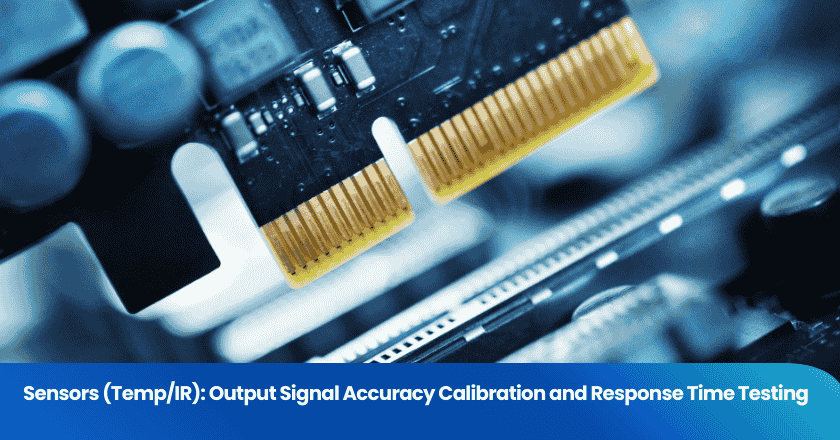
You've sourced a batch of temperature or infrared sensors from a Chinese manufacturer. The datasheet shows ±0.5°C accuracy and a response time of under two seconds. But how was that specification tested? Was it measured on each unit individually, or was it established on a sample batch at design qualification and then assumed for all subsequent production? And when ambient conditions on the factory floor differ from those stated in the datasheet, does the calibration still hold?
For buyers sourcing sensors for industrial, HVAC, automotive, medical, or IoT applications, these are not theoretical questions — they are the difference between a shipment that performs in the field and one that generates a wave of customer complaints. This guide explains how output signal accuracy calibration and response time testing are properly conducted for contact temperature sensors (NTC thermistors, RTDs, thermocouples) and non-contact infrared (IR) sensors, what standards govern each, and what a quality inspection or factory audit should verify before you accept a shipment.
Key Takeaways
- A true temperature sensor calibration requires comparison against a certified reference in a stable temperature environment — checking a sensor's output against another display reading is verification, not calibration.
- The standard method for response time testing is the plunge test: the time for the sensor to reach 63.2% of a step change in temperature (the time constant τ), measured by sudden immersion in a controlled liquid bath.
- For IR sensors, calibration accuracy depends critically on emissivity settings and the use of a blackbody reference source with emissivity ≥0.95; a factory using a flat-plate reference without radiometric calibration cannot claim traceable IR accuracy.
Why Sensor Calibration Matters at the Factory Level
The gap between datasheet specification and delivered accuracy
Many sensor manufacturers establish their accuracy specifications at design qualification — testing a sample population to confirm the design meets its stated tolerance — and then manage production through statistical process control rather than individual unit calibration. The result is a shipped batch that conforms on average but contains outliers. What many suppliers describe as a "calibration certificate" is often closer to a batch validation record — a sample is tested, accepted, and the entire batch is released under that certificate. This does not constitute individual unit calibration and provides no assurance that any specific sensor you received is within specification.
For buyers who use sensors in applications with safety, regulatory, or precision implications — process temperature monitoring, fever screening, industrial automation — the distinction is material. ISO/IEC 17025 is the safest accreditation standard for sensor calibration, requiring four-eye approval, documented measurement uncertainty at each calibration point, and traceable reference standards accredited by national bodies such as NIST (US), UKAS (UK), or DAkkS (Germany).
What "traceable calibration" actually means
A temperature calibration compares the device under test against a reference sensor that has been calibrated in an accredited laboratory under controlled, stable temperature conditions. The reference sensor's accuracy is itself traceable to national or international temperature standards — typically the International Temperature Scale of 1990 (ITS-90). Without this traceable chain, a manufacturer's accuracy claim is self-referential and unverifiable.
Buyers specifying sensors for regulated markets (medical devices, pharmaceutical cold chain, food safety) should require calibration certificates that specify the calibration laboratory's accreditation body, the reference standard used, the measurement uncertainty at each test point, and the environmental conditions during calibration. A certificate that states only "calibrated to ±0.5°C" without this information is not a calibration certificate in the ISO 17025 sense.
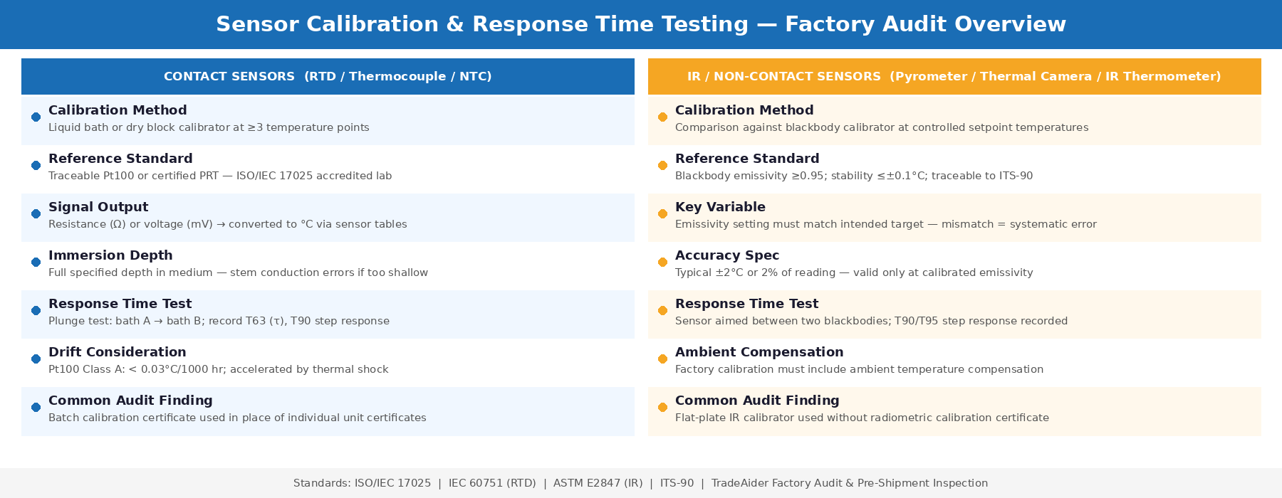
Calibrating Contact Temperature Sensors (RTDs, Thermocouples, NTCs)
The calibration process step by step
Contact temperature sensors — RTDs (Resistance Temperature Detectors), thermocouples, and NTC thermistors — share a common calibration approach. The sensor under test and a calibrated reference sensor are both immersed in a temperature-stable medium — either a liquid calibration bath or a dry block calibrator — and their outputs are compared at multiple defined temperature points across the sensor's operating range.
The calibration steps auditors and buyers should ask about are: stabilization (confirming the temperature source and sensors have reached thermal equilibrium before recording readings), immersion depth (the sensor must be inserted to the manufacturer's specified depth to prevent stem conduction errors), reference traceability (the reference sensor must have a valid calibration certificate from an accredited laboratory), and documentation (as-found and as-left values recorded for each calibration point, with calculated deviation and uncertainty).
Immersion depth is a critical and frequently overlooked factor. If the sensor is not inserted deep enough into the temperature source, heat conduction along the sensor body distorts the reading — producing a result that appears accurate in the calibration record but will read incorrectly when installed at the correct depth in its application.
Common calibration approaches by sensor type
| Sensor Type | Signal Output | Calibration Medium | Typical Accuracy Range |
|---|---|---|---|
| Pt100 / Pt1000 RTD | Resistance (Ω) | Liquid bath, dry block | Class A: ±0.15°C + 0.002|t| |
| Thermocouple (K, J, T) | Voltage (mV) | Liquid bath, dry block | Class 1: ±1.5°C or ±0.4% |
| NTC Thermistor | Resistance (kΩ) | Liquid bath (mineral oil) | ±0.1–0.5°C depending on grade |
| 4–20 mA transmitter | Current (mA) | Liquid bath + loop calibrator | Depends on sensor + transmitter |
For sensors that transmit a 4–20 mA current signal — a common format for industrial process sensors — the standard current signal has been used for decades because it can be transmitted over long distances without the signal loss that affects voltage signals. Calibrating a 4–20 mA transmitter system requires verifying both the sensing element accuracy (against a reference at the calibration bath) and the transmitter output (with a loop calibrator measuring actual current output at defined temperature set points). Checking only the display reading without verifying actual current output is not a complete system calibration.
Drift and recalibration intervals
Temperature sensors drift over time. A well-designed Pt100 RTD operated within its rated conditions typically drifts less than 0.03°C per 1000 operating hours — meaning calibration integrity remains within ±0.5°C specification for years under normal conditions. However, sensors exposed to thermal shock, vibration, contamination, or temperatures near their rated maximums drift faster. For production lots sourced from Chinese factories, drift is rarely the problem at incoming inspection — out-of-specification accuracy from manufacturing variability and inadequate individual unit calibration is more commonly what buyers discover when they independently verify sensor accuracy on arrival.
Calibrating Infrared (IR) Sensors
Why IR calibration is fundamentally different
Non-contact infrared sensors — thermometers, pyrometers, and thermal imaging sensors — do not measure temperature directly. They measure the intensity of infrared radiation emitted by a surface and convert it to a temperature value using Planck's radiation law and an assumed emissivity value. This means IR sensor accuracy depends not only on the detector's sensitivity and the electronics' signal processing, but also on how well the emissivity assumption matches the target being measured.
Most IR sensor datasheets show an accuracy specification of ±2°C or 2% of reading — but this specification is only valid when the sensor is pointed at a target with the emissivity value assumed during calibration. An incorrect emissivity setting can introduce errors of several degrees without any fault in the sensor hardware itself. This is why the emissivity setting, target material, and measurement distance are all part of a properly documented IR calibration procedure.
Blackbody reference sources: the standard for IR calibration
IR sensors are calibrated by pointing them at a blackbody calibrator — a device that generates known, stable infrared radiation at a controlled temperature with very high emissivity (typically ≥0.95). If the emissivity of the radiation source equals 1.00, as is the case with a blackbody calibrator, then its output is known precisely at any given temperature. A flat-plate IR calibrator, by contrast, typically has emissivity in the 0.93–0.97 range and must be radiometrically calibrated to provide traceable accuracy — a step many lower-cost factory calibration setups skip.
The blackbody calibrator should have stability and uniformity of better than ±0.1°C for high-precision calibration, and it should be annually calibrated against certified standards and kept clean to prevent emissivity drift — particularly important for cavity-type blackbodies where contamination of the cavity interior directly affects emissivity. Buyers auditing a sensor factory should ask to see the blackbody calibrator's own calibration certificate, not just the sensor calibration records it was used to produce.
Contact Temperature Sensor vs IR Sensor — Calibration Methods and Response Time Testing Overview
Emissivity errors and how they compound
Emissivity is an object's ability to emit infrared radiation compared to a perfect blackbody, and if it is not correctly accounted for, the surface temperature reading may appear to be higher than it actually is. For production inspection of IR sensors, buyers should request evidence of the emissivity value used during calibration, confirmation that the calibration emissivity matches the intended target material, and traceability documentation showing the blackbody calibrator's certified temperature at each calibration point.
A factory calibrating an IR sensor intended for measuring human skin temperature (emissivity approximately 0.98) against a blackbody at emissivity 0.95 without correction introduces a systematic error. Auditors from TradeAider's factory audit team check calibration procedure documentation specifically for emissivity setting consistency between the calibration setup and the sensor's intended application.
Response Time Testing for Temperature and IR Sensors
Defining the time constant
Response time is defined in terms of a time constant — the time necessary for a temperature sensor to respond to 63.2% of a step change in temperature. This 63.2% threshold (τ, tau) derives from the exponential nature of thermal response: a sensor responding exponentially to a step change will have reached 63.2% of the final temperature after one time constant, 86.5% after two, and approximately 99.3% after five. When a datasheet specifies a response time of "0.5 seconds," it typically refers to τ — the time to 63.2% of the step change — not the time to reach full equilibrium, which is several times longer.
The plunge test: standard factory method for contact sensors
The standard method for measuring temperature sensor response time is the plunge test. In practice, the temperature sensor is dipped from one water bath to a second water bath at a significantly different controlled temperature (for example, 25°C to 90°C), while a reference sensor monitors both baths. The time until the sensor under test reaches the target bath temperature is recorded, producing a step response curve from which T63 (τ) and T90 are calculated.
The time constant can be determined by calculating when the sensor temperature changed by 63.2% between any two measured points. Proper plunge test execution requires that both baths are at stable temperatures before the test begins, that the sensor reaches full equilibrium in the first bath (including self-heating from measurement current for RTDs), and that the insertion into the second bath is rapid and consistent. Variation in insertion speed is a source of test-to-test variability that factories running manual plunge tests often underestimate.
| Response Time Metric | Definition | Significance |
|---|---|---|
| T63 (τ, time constant) | Time to reach 63.2% of step change | Primary response time specification; used for sensor comparison |
| T90 | Time to reach 90% of step change | Often cited in process control; ≈ 2.3τ for exponential response |
| T99 (settling time) | Time to reach 99% of step change | ≈ 5τ; time for sensor to fully stabilise at new temperature |
Response time testing for IR sensors
IR sensors respond to changes in the infrared radiation received at their detector — which is a function of both the target temperature and the detector's own thermal mass and electronics settling time. For contactless sensors, response time is specified differently than for contact sensors: it is typically the time for the sensor's displayed output to stabilise at 90% or 95% of the step change when the sensor is pointed from one blackbody target to another at a significantly different temperature.
The test methodology must be carefully controlled — particularly for NTC thermistor-based sensors, where the loading current (the measurement current flowing through the thermistor) causes self-heating that shifts the measured temperature. A factory that does not account for self-heating in its response time test setup is measuring a different condition than its datasheet specification was derived from.
What a Pre-Shipment Inspection Verifies for Sensor Lots
Documents to request
Before accepting a shipment of temperature or IR sensors, buyers should request the following from the manufacturer: individual calibration certificates (not batch validation records), the calibration laboratory's accreditation certificate specifying ISO/IEC 17025 scope, the blackbody calibrator's own calibration certificate (for IR sensors), production test data showing response time measurements for the shipped lot, and the calibration procedure document specifying emissivity settings, immersion depths, temperature points tested, and stabilisation criteria.
The absence of any of these documents is a significant finding. It means the factory either does not have a complete calibration system or is unable to produce records for the specific production lot — both of which are reasons for an on-site investigation before accepting delivery.
What incoming inspection can verify
During a pre-shipment inspection, inspectors can perform spot-check accuracy verification against a calibrated reference — confirming that a sample of sensors from the lot fall within the specified accuracy tolerance at one or more temperature points. This is not a full re-calibration but provides evidence that the factory's production process has not introduced systematic errors in the shipped batch.
Response time can be spot-checked using a simplified plunge test for contact sensors, or by observing the sensor output when pointed between two stable temperature references for IR sensors. Any sensor in the sample that exceeds its specified T63 or T90 by more than 20% indicates a potential production consistency problem worth investigating at the factory level — either through a factory audit or a during-production inspection of the next lot.
For complex sensor production lines where calibration documentation and process traceability are important specifications, TradeAider's team can design audit scope to specifically review calibration equipment, reference traceability records, and production test coverage — giving buyers the visibility they need to make informed acceptance decisions.
Frequently Asked Questions
What is the difference between a plunge test and a response time specification on a datasheet?
The plunge test is the laboratory method used to measure a sensor's time constant (τ) by suddenly immersing it in a fluid at a different temperature and recording its output over time. The response time on a datasheet is derived from this test — typically T63 (63.2% of step change) or T90 — under specific test conditions of fluid type, flow rate, and temperature differential. These conditions must be identical for comparison to be valid. Datasheets frequently specify response time in stirred water at a defined flow velocity, so sensors used in still air or viscous fluids will have significantly longer actual response times than the datasheet figure.
Can a factory's own calibration records be trusted without third-party verification?
Factory-issued calibration records are only as reliable as the factory's calibration infrastructure — the quality of their reference equipment, the traceability of that equipment to national standards, the rigour of their measurement procedures, and the independence of their quality system. Without seeing the calibration laboratory's accreditation scope and the reference sensor's own traceable certificates, a buyer cannot confirm that a factory calibration record reflects the accuracy that the certificate claims. Third-party verification — either through an accredited incoming inspection or an independent re-calibration of a sample — is the only way to obtain independent assurance.
What accuracy can buyers realistically expect from Chinese-manufactured temperature sensors?
Chinese manufacturers produce sensors across the full quality spectrum — from commodity NTC thermistors with ±1°C accuracy suitable for consumer appliances to precision Pt100 RTDs meeting IEC 60751 Class A (±0.15°C) or better for industrial instrumentation. The accuracy level achievable depends on the manufacturing process, component grade, and calibration infrastructure — not on geography. What varies significantly between manufacturers is the calibration depth: whether accuracy is verified on every unit, on a sample, or only at design qualification. Buyers specifying high-accuracy sensors should contractually require individual unit calibration certificates with stated measurement uncertainty and reference traceability before shipment.
Why does emissivity matter so much for IR sensor calibration?
IR sensors measure radiated energy, not temperature directly. The conversion from measured radiation to temperature depends on how efficiently the target surface emits infrared radiation — its emissivity. A surface with emissivity 0.90 emits 10% less radiation than a perfect blackbody at the same temperature, so an IR sensor calibrated to a blackbody (emissivity 1.0) will read that surface as cooler than it actually is unless emissivity correction is applied. This makes emissivity the most common source of systematic error in IR temperature measurement — and the most important parameter to verify during calibration documentation review for any IR sensor application involving real-world targets.
Related Articles


Grow your business with TradeAider Service
Click the button below to directly enter the TradeAider Service System. The simple steps from booking and payment to receiving reports are easy to operate.