- About Us

- Our Services
- Your Industry
- Resources
- News & Blog
Wire harnesses are among the most failure-prone components in consumer electronics, industrial equipment, and automotive products — and among the most difficult to inspect without the right tests. A harness that looks correct in a carton, with neatly dressed wires and properly seated connectors, can have crimp terminations that will pull apart under vibration load or wires routed to the wrong pins that will cause a product to malfunction the first time power is applied. Neither failure shows up in a visual check. Both are routine findings in a properly conducted pre-shipment inspection.
This guide covers the two essential wire harness inspection disciplines: terminal crimp pull force testing and wire sequence continuity verification. It explains what each test measures, what standards govern acceptable performance, and how third-party inspection applies these tests to production batches before goods leave the factory.
Key Takeaways
- Terminal crimp pull force testing is a destructive test that measures the force required to separate a terminal from its wire — the primary standard is IPC/WHMA-A-620, which requires crimp strength to meet at least 60–90% of the wire's ultimate tensile strength depending on application class.
- Wire sequence continuity testing (100% rule) verifies that every circuit in a harness has an unbroken path, no unintended shorts, and no miswires — statistical sampling is not acceptable for continuity; every harness must be tested.
- 25% of electrical failures in automotive products are attributed to bad crimps — poor tool calibration and terminal-to-wire size mismatches are the leading causes.
- Re-crimping a failed terminal is not permitted under any quality standard — defective crimps must be cut and replaced, making process control during production the only effective prevention.
Terminal Crimp Pull Force Testing
What a Crimp Pull Force Test Measures
A crimp connection joins a wire to a terminal by deforming the terminal barrel around the wire strands under high pressure, creating metal-to-metal contact across the full strand bundle. The mechanical integrity of this joint — its resistance to the tensile forces that occur during installation, vibration, and thermal cycling — is measured by the pull force test, also called the pull-and-break test.
The standard pull force test procedure clamps the terminal in a fixed fixture and the wire in a motorized grip, then applies tensile force at a controlled rate — typically 25 mm/minute for IPC/WHMA-A-620 — until the joint separates. The measured peak force is compared against the minimum threshold for the wire gauge and application class. If the terminal separates from the wire before reaching the minimum force, the crimp fails. If the wire breaks before the terminal separates, the crimp passes — the wire itself was the limiting factor, which is the ideal outcome of a well-executed crimp.
The IPC/WHMA-A-620 Standard and Minimum Force Values
The governing standard for wire harness and cable assembly quality worldwide is IPC/WHMA-A-620, developed jointly by IPC and the Wire Harness Manufacturers Association. IPC/WHMA-A-620 specifies that crimp pull-off force must reach at least 90% of the wire's ultimate tensile strength — for a 20 AWG wire, this translates to approximately 25 lbf (111N) minimum. IPC A-620 sets a general floor of 60% of the wire's tensile strength across all application classes, with Class 3 (high-performance and harsh environment, including medical and aerospace) requiring the highest thresholds.
The table below shows minimum pull force requirements for common wire gauges under IPC/WHMA-A-620:
| Wire Gauge (AWG) | Min Pull Force (IPC/WHMA-A-620) | Typical Application | Failure Mode if Below Threshold |
|---|---|---|---|
| 28 AWG | ≥5N (1.1 lbf) | Fine signal wiring, sensors | Terminal pullout under vibration |
| 22 AWG | ≥22N (5 lbf) | Low-power signal harnesses | Intermittent connection during handling |
| 20 AWG | ≥58N (13 lbf) | General power/signal harnesses | Joint separation under installation load |
| 18 AWG | ≥80N (18 lbf) | Automotive, industrial power | Thermal cycling-induced failure |
Root Causes of Crimp Pull Force Failures
Industry research attributes approximately 25% of all electrical failures in automotive and electronic products to bad crimps, with poor crimping tool calibration and terminal-to-wire size mismatch as the leading root causes. Three defect categories dominate field findings. First, tool wear — a crimping applicator that has run beyond its maintenance interval produces progressively shallow crimp heights, reducing barrel compression and joint strength systematically across a production run. This is a batch-correlated defect: if one sample fails on tool wear, the entire batch produced since the last tool change is at risk. Second, terminal-to-wire mismatch — using a terminal rated for a wire range of 26–20 AWG on a 26 AWG wire leaves air gaps inside the crimp barrel that visual inspection cannot detect, as the outer dimensions look correct. Third, tinned strands — soldering or pre-tinning wire strands before crimping is prohibited under IPC/WHMA-A-620 because solder migrates and cracks under compression, producing a connection that passes visual inspection but fails under mechanical load.
Re-crimping a failed terminal is explicitly prohibited under IPC/WHMA-A-620 — the correct response to a substandard crimp is to cut the terminal off and replace it with a new one. Any supplier that re-crimps rejections is generating counterfeit-passing results, not fixing the underlying defect.
When Pull Testing Should Be Performed
Best-practice pull testing frequency requires testing at the start of every production shift, every time a crimping applicator is changed, and every time a new wire reel is loaded. This frequency is driven by the batch-correlation of tool wear defects — a pull test that finds a failure identifies the point at which calibration was lost, allowing the manufacturer to quarantine and re-inspect only the units produced since the last passing test. Suppliers who perform pull testing "once a week" or only at the start of a production run are not providing adequate process control.
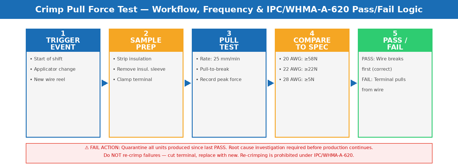
Figure 1: Crimp pull force test workflow — frequency requirements, pass/fail decision logic, and defect classification per IPC/WHMA-A-620.
Wire Sequence Continuity Testing
What Continuity Testing Verifies
Wire sequence continuity testing verifies three things simultaneously: that every circuit in the harness has an unbroken path from terminal to terminal (continuity — no open circuits), that no unintended connections exist between circuits that should be isolated (no shorts), and that every wire is connected to the correct pin in the correct connector (no miswires). A harness can pass visual inspection on all three dimensions and still fail all three — the visual appearance of a properly connected harness is identical to one with a swapped wire pair or a short from a strand that crossed during assembly.
Continuity testing using automated harness testers works by energizing each conductor sequentially and comparing the measured connectivity map against a "golden sample" program — the schematic of a verified correct harness. Any deviation from the expected connectivity pattern — an open circuit where continuity should exist, a low-resistance path where isolation should exist, or a conductor mapped to a different pin than specified — triggers an instant fail indication that stops the tested unit from proceeding.
The 100% Testing Rule
Unlike most quality inspection disciplines where statistical sampling is appropriate, wire harness continuity testing follows a 100% rule — every harness produced must be tested, not a statistical sample. This requirement comes from the nature of the defect: miswiring, shorts, and open circuits are not distributed randomly across a batch by production variation. They are discrete, unit-specific errors made at the individual assembly station. A batch of 500 harnesses where one operator made a consistent wire swap on their production subset could have 80 units with identical miswires and 420 fully correct units. AQL sampling would have a high probability of missing the defective subset entirely. 100% continuity testing catches every defective unit regardless of the defect distribution pattern.
Modern automated continuity testers scan thousands of test points per second, making 100% testing of even complex multi-circuit harnesses practical on production-line timescales. For buyers sourcing harnesses from Chinese factories, the correct audit question is not "do you perform continuity testing?" but "do you perform 100% continuity testing with automated test equipment, and do you have test records for every serial number?" Suppliers that answer "we sample" or "we test key circuits" are not operating to the 100% standard and are shipping statistical risk with every batch.
Types of Continuity Defects and Their Field Consequences
The defect taxonomy for wire harness continuity failures maps directly to field failure modes. Open circuits — broken conductors or unseated terminals — produce dead circuits that fail immediately on first use; these are the most visible and most likely to generate immediate returns. Short circuits — unintended contact between conductors — can range from immediately destructive (powering a signal line from a power line) to intermittent (two adjacent wires that short only when the harness flexes in installation). Miswires — correct conductors, wrong pin assignment — are the most dangerous continuity defect because their consequence depends on the circuit function: a miswire on a non-critical signal produces a product that operates incorrectly; a miswire on a power circuit can destroy the connected device or create a safety hazard.
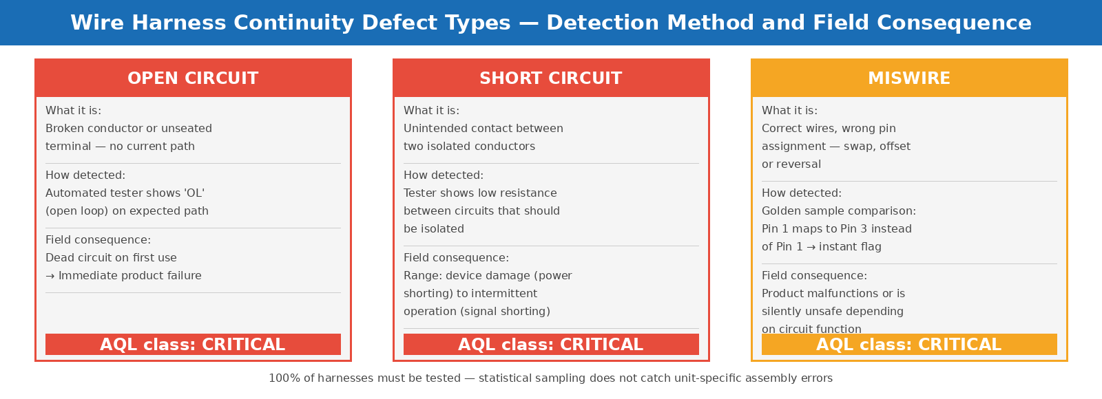
Figure 2: Wire harness continuity defect types — how each is detected during testing and what it means for the product in the field.
Applying These Tests in Pre-Shipment Inspection
What to Request from Your Supplier
For buyers sourcing wire harnesses or harness-integrated products from Chinese factories, the pre-shipment inspection protocol should cover both disciplines. For crimp quality, buyers should specify IPC/WHMA-A-620 as the governing standard and request pull force test records for the production batch — specifically, records showing test dates, wire gauges tested, measured values, and tool change events. Pull test records that show suspiciously uniform values (every sample at exactly the minimum threshold) warrant investigation, as they can indicate that pull testing is being performed as a check-the-box exercise rather than as genuine process monitoring.
For continuity, buyers should request 100% test completion records for the batch, specifying that every serial number was tested against the correct harness schematic. Acceptable continuity test documentation identifies the tester model used, the test program version (tied to the engineering schematic revision), and pass/fail results per unit. A factory that cannot produce these records for the production batch being inspected has not performed 100% continuity testing — regardless of what they claim in a supplier questionnaire.
The Role of Third-Party Pre-Shipment Inspection
A third-party inspector at pre-shipment verifies two categories of evidence: supplier process records and independent functional sampling. Process record verification covers pull test logs, continuity test records, and tool calibration certificates. Independent functional sampling uses the inspector's own continuity tester on a random sample from the production batch — the inspector's sample test is an independent check on whether the supplier's 100% testing is being performed correctly, not a replacement for it.
For complex harnesses where the test schematic is proprietary, buyers should include a verified "golden sample" — a confirmed-correct harness unit — with their inspection order, allowing the inspector to use it as the reference for comparative continuity testing on production samples. This approach is particularly important for buyers who have experienced miswiring issues with a supplier in previous batches, as it directly tests whether the corrective action actually resolved the root cause.
TradeAider's pre-shipment inspection service covers harness functional testing as part of electronics product inspection, with online real-time reporting that allows buyers to specify harness test focus — crimp sampling, continuity verification, or both — and receive photographic evidence of test results within 24 hours of inspection completion.
For electronics buyers who also need to verify product compliance testing beyond harness quality, TradeAider's product testing services cover laboratory-grade qualification testing for components and finished goods. And for a framework covering the full electronics QC process from incoming materials through pre-shipment, the electronics quality control guide covers the complete methodology.
Frequently Asked Questions
What is the difference between a Class 2 and Class 3 wire harness for pull force requirements?
IPC/WHMA-A-620 defines three product classes. Class 2 covers dedicated service electronics — commercial products where reliability is important but continuous operation is not life-critical, such as computers and industrial equipment. Class 3 covers high-performance and harsh environment applications — military, aerospace, and medical devices where failure is not an option. Class 3 requirements for crimp pull force, visual inspection magnification, and process documentation are significantly more stringent than Class 2. For consumer electronics and standard industrial products sourced from China, Class 2 is the baseline minimum; for any product with safety implications, Class 3 should be specified.
Can visual inspection replace pull force testing for crimp quality?
Visual inspection cannot replace pull force testing for crimp quality verification. A visual inspection can detect extreme crimps — a barrel that was never compressed, or a wire that missed the barrel entirely — but cannot detect the more common failure modes: shallow crimp height from a worn tool, terminal-to-wire size mismatch, or tinned strands that create an internally weak joint. IPC/WHMA-A-620 allows crimp height measurement (a dimensional check) as an alternative to destructive pull testing within the same test batch, but a dimensional check alone does not verify the wire-to-terminal interface quality that pull force testing directly measures.
How should I handle a batch where continuity testing records are missing or incomplete?
A batch without complete 100% continuity test records is unacceptable regardless of how good the visual inspection results appear. The correct response is to hold the shipment and request that the factory perform 100% continuity testing before release, with test records provided to the buyer as part of the inspection documentation. If the factory is unable to demonstrate 100% continuity testing capability — no automated tester, no test program for the product — this is a fundamental process gap that warrants escalation beyond the current order to supplier qualification review.
What connection resistance threshold indicates a failing harness circuit?
For low-current signal circuits, connection resistance above 2.5 ohms at any terminal junction is a concern that warrants investigation. Resistance testing using a four-wire milliohm meter provides more precise measurement than standard continuity testing, which can pass circuits with marginally high resistance. For power circuits in harnesses, junction resistance should be measured against the design specification's maximum allowable voltage drop at the rated current — a 10-milliohm connection in a 10-ampere circuit drops 100 millivolts, which may be acceptable or unacceptable depending on the application.
Wire harness failures discovered after shipment require costly rework, generate product returns, and in safety-critical applications can create liability exposure that far exceeds the cost of the harness itself. TradeAider's pre-shipment inspection service covers crimp pull force sampling and continuity verification as part of electronics product inspection, with an official report within 24 hours and real-time visibility for buyers. Contact TradeAider to discuss harness inspection requirements for your next shipment, or use the Inspection Charge Calculator to estimate inspection costs.

Related Articles
Grow your business with TradeAider Service
Click the button below to directly enter the TradeAider Service System. The simple steps from booking and payment to receiving reports are easy to operate.