- About Us

- Our Services
- Your Industry
- Resources
- News & Blog
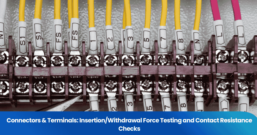
A connector that inserts too easily may back out under vibration. One that requires too much force may damage the mating housing during assembly—or prevent a field technician from ever disconnecting it. A terminal with elevated contact resistance generates heat in proportion to the current squared, quietly degrading performance until failure. These are not exotic failure modes. They are the everyday consequences of skipping two specific quality checks—insertion/withdrawal force testing and contact resistance measurement—that experienced connector buyers treat as non-negotiable. For global buyers sourcing wiring harnesses, cable assemblies, or any product with multi-contact connectors from Chinese factories, this guide explains what these tests measure, what standards govern them, what defects they detect, and how to incorporate them into your pre-shipment inspection and supplier qualification process.
Key Takeaways
- Insertion force and withdrawal force must be balanced—too low risks accidental disconnection; too high risks housing damage and assembly errors.
- IEC 60512-13-2 and BS EN 5057 are the primary standards covering insertion and withdrawal force testing for electrical connectors across multiple mating cycles.
- Contact resistance must be measured using the four-wire (Kelvin) method—standard two-wire multimeter measurements include lead resistance and will give inaccurate readings at the milliohm level.
- Elevated contact resistance is a direct fire risk in connectors carrying current above 1A: by Joule's law (P = I²R), even a small increase in resistance creates disproportionate heat generation.
- The ideal crimp failure mode is wire breakage, not terminal pullout—this confirms the crimp is stronger than the wire itself, as required by IPC/WHMA-A-620.
Why Connectors and Terminals Are a QC Priority for Electronics Buyers
The Hidden Cost of Connector Failures
Connectors are among the most failure-prone components in any electronic assembly—not because they are poorly designed, but because they are highly sensitive to manufacturing process variables that simple visual inspection cannot detect. A terminal crimped 0.1 mm too high may look acceptable under normal inspection but will exhibit elevated resistance and reduced pull force. A connector housing with a slightly undersized locking lance may insert smoothly but will disengage under the vibration levels common in consumer electronics shipping. These failures don't surface during factory QC—they surface during customer use, where the cost of a return is orders of magnitude higher than the cost of the test that would have caught it. For buyers sourcing connectors in China, where sub-supplier component quality is a known variable, the insertion/withdrawal force test and contact resistance check are the two most reliable indicators that connector quality is within specification.
What Types of Products Are Most Affected
Insertion and withdrawal force and contact resistance issues affect any product with multi-pin connectors: consumer electronics with USB, HDMI, or proprietary charging connectors; power tools with battery packs that mate and unmate repeatedly; appliances with internal wiring harnesses; LED lighting with plug-in driver assemblies; and industrial control equipment with multi-contact terminal blocks. The higher the current the connector carries and the more frequently it is mated and unmated during product life, the greater the consequence of force and resistance deviations. A poorly crimped terminal in a 5V data line may cause a signal error. The same defect in a 10A power connector is a potential fire hazard—a relationship defined by Joule's law and confirmed by contact testing standards that specifically limit temperature rise under rated current.
Insertion and Withdrawal Force Testing
What the Test Measures and Why It Matters
Insertion and withdrawal force testing applies controlled compressive and tensile forces to a mating connector pair to measure the force required to fully mate the connectors (insertion force) and the force required to fully unmate them (withdrawal force). These two measurements reflect the quality of the contact geometry, the spring force of the contact elements, and the dimensional accuracy of the housing. A well-designed connector must balance sufficient engagement force to prevent accidental disconnection with an acceptable withdrawal force to allow servicing—and this balance must remain stable across the specified mating cycle life. The test is governed by several international standards: IEC 60512-13-2 covers insertion and withdrawal force testing across multiple mating cycles for electrical connectors; BS EN 5057 covers cycle testing of insertion and withdrawal forces with focus on connector performance under repeated use; and IEC 61210 specifies extraction force requirements for terminal connectors.
The Two Mechanical Phases of Connector Mating
Understanding why insertion force is typically higher than withdrawal force requires understanding the mechanical stages of mating. During insertion, the connector contacts go through two sequential stages. The spreading stage occurs as the contact beams are forced apart by the entering pin or tab—this requires overcoming both friction and the spring force of the contact beam. The sliding stage follows once the contacts are fully spread, and requires only friction force as the contact slides to its mated position. During unmating, there is no spreading effect—only friction must be overcome, which is why withdrawal force is characteristically lower than insertion force for most connector types. When withdrawal force is higher than expected—or higher than insertion force—it typically indicates a housing latch or locking feature that is contributing to retention, a component of connector design that must be factored into the force specification.
What Defects This Test Reveals
Force testing at incoming inspection or pre-shipment catches several categories of manufacturing defects that visual inspection misses. Contact spring force out of specification—caused by contact material with incorrect temper, incorrect contact geometry from die wear, or bent contact beams during assembly—shows as insertion force above or below the specified range. Housing dimensional non-conformances that cause the connectors to bind during mating produce abnormally high peak insertion forces or asymmetric force-displacement profiles. Under-tensioned locking features produce withdrawal forces below the minimum retention specification, meaning the mated connector pair will disengage under forces encountered in normal use. Contamination of contact surfaces with oil, flux residue, or oxide films changes the friction coefficient and can produce erratic force values even when the underlying geometry is correct. Force-displacement curves generated during testing—showing the full profile from initial contact to full engagement—allow these failure modes to be distinguished from each other by their characteristic shape.
Test Equipment and Procedure
Production-level insertion and withdrawal force testing uses motorized tensile test systems equipped with load cells calibrated for the force ranges relevant to the connector type—typically 1 N to 300 N for consumer electronics connectors. The connector and its mating half are mounted in precision alignment fixtures that eliminate transverse forces perpendicular to the mating axis; any off-axis loading adds to the measured force in ways that cannot be separated from genuine connector force characteristics. The test system moves at a controlled, defined rate—typically 25.4 mm/minute per standard test procedures—and records peak force and force-displacement profile. For durability qualification, the test is run through the connector's rated mating cycle count (commonly 500 to 2,000 cycles per the connector specification), with force and contact resistance measured at defined intervals throughout.
Contact Resistance Testing
Why a Standard Multimeter Is Insufficient
The resistance of a properly formed crimp terminal contact interface is typically in the range of 0.5 to 5.0 milliohms for standard applications. A standard two-wire digital multimeter (DMM) in resistance mode typically contributes 100 to 200 milliohms of its own lead resistance to the measurement—a value greater than what is actually being measured. Using a two-wire DMM to verify contact resistance in the milliohm range is not just imprecise; it is fundamentally incapable of distinguishing a good connection from a bad one at the specification level. The solution is the four-wire Kelvin method, which uses separate current-carrying and voltage-sensing circuits to completely eliminate the effect of lead resistance from the measurement. With a Kelvin-connected measurement system, the resistance reading reflects only the contact interface under test—not the fixture, not the test leads, not the connection between lead and DUT.
What Elevated Contact Resistance Indicates
Contact resistance above the specification limit for a crimp terminal is a physical indicator of inadequate metal-to-metal contact at the crimp interface. The most common causes are: insufficient crimp force leaving air gaps between conductor strands and the terminal barrel; over-crimping that fractures conductor strands, reducing contact area; incorrect crimp height (too high or too low relative to the manufacturer's specification); contaminated contact surfaces (oxidation, flux residue, moisture); incorrect wire gauge or stranding for the terminal; and insulation material caught in the crimp area due to incorrect stripping length. Milliohm-sensitive four-wire measurement can locate bad solder joints, faulty crimps, recessed pins, pin contact contamination, improper wire gauge, and stress-extruded wire—defects that would be missed entirely by less sensitive measurement methods.
The Thermal Consequence of High Contact Resistance
The safety implication of elevated contact resistance is quantified by Joule's law: power dissipated at a resistance equals current squared times resistance (P = I²R). A contact interface with 5 mΩ additional resistance in a 10A power circuit dissipates 500 mW of additional heat at that junction—localized heat generation that degrades insulation, accelerates contact oxidation, and can ignite adjacent materials over time. The standard temperature rise limit for contact effectiveness testing is 52 Kelvin above ambient—a threshold derived from the thermal degradation characteristics of PVC insulation and the oxidation rate of copper alloys. Buyers sourcing power connectors, battery connectors, or any connector carrying sustained current should treat contact resistance acceptance criteria as a safety specification, not just a performance specification.
Crimp Height Measurement: The Dimensional Proxy for Contact Quality
Because contact resistance testing at 100% production volume requires tester infrastructure not always available at Chinese connector factories, the dimensional measurement of crimp height serves as a critical in-process proxy for crimp quality. Crimp height is the cross-sectional height of the conductor crimp barrel after compression, measured with a precision micrometer calibrated to ±0.001 mm accuracy. The connector manufacturer specifies a target crimp height and tolerance for each wire gauge and terminal combination—a tolerance that may be as small as 0.05 mm for fine-pitch connectors. Crimp height within specification correlates with adequate compression, full conductor strand contact, and resistance values within range. Crimp height outside specification—either too high (under-crimped) or too low (over-crimped)—predicts both mechanical and electrical failure. This dimensional measurement is non-destructive, fast, and applicable to 100% production inspection when process stability is in question.
Common Connector Defects and Their QC Consequences
| Defect | Cause | Detection Method | Risk if Missed |
|---|---|---|---|
| Low insertion force | Worn contact die, incorrect contact geometry | Force test, force-displacement curve | Connector disconnects in use; intermittent signal/power |
| High insertion force | Oversized contact, housing dimensional error | Force test, housing dimensional check | Damaged housing during assembly; bent contact pins |
| Low withdrawal / retention force | Weak locking lance, under-tensioned contact spring | Withdrawal force test | Connector backs out under vibration or cable pull |
| High contact resistance | Under/over-crimp, contamination, wrong wire gauge | 4-wire Kelvin resistance, crimp height measurement | Heat generation, signal degradation, fire risk at high current |
| Low pull-out / wire retention force | Insufficient crimp force, wrong crimp height, short strip length | Destructive pull test per IEC 60512-16-4 | Wire separates from terminal under cable stress; open circuit |
| Oxidation / tin whiskers on contacts | Improper plating, storage conditions, pure tin plating | Visual with magnification, contact resistance post-cycling | Intermittent contact failure; shorts from whisker growth |
| Insulation caught in crimp | Incorrect strip length, tooling misalignment | Cross-section analysis, force+intermittence test | No metal-to-metal contact; connection fails immediately or intermittently |
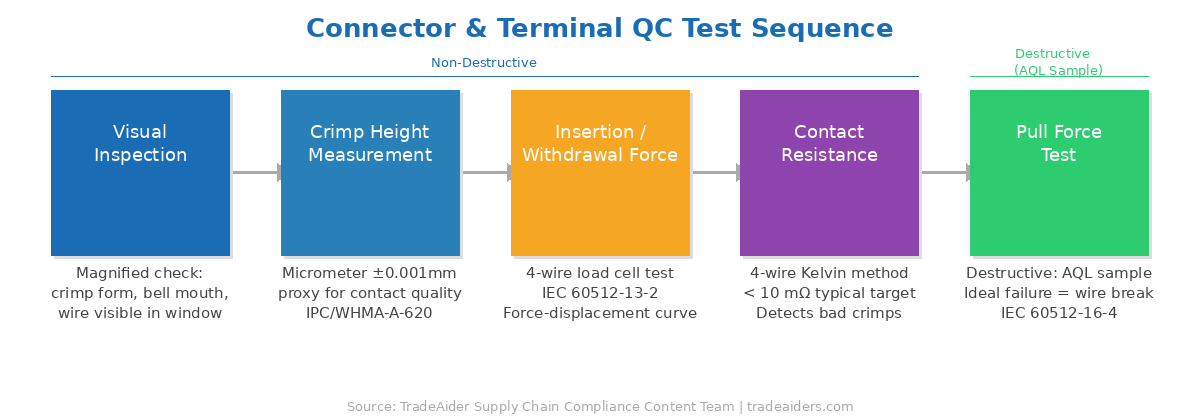
Connector QC test sequence: visual inspection → crimp height → insertion/withdrawal force → contact resistance → pull force
Applying These Tests in a China Sourcing Context
What to Verify at the Pre-Production Stage
The connector and terminal quality control process begins before production—at the incoming material stage. A Pre-Production Inspection for a product containing connectors should verify that the incoming connector components—housings, contact terminals, and wire materials—have the correct specifications for the application. This includes confirming that terminal plating (gold vs. tin) matches the specification, that wire gauge matches the terminal's rated range, and that the factory has the correct crimping tooling for the specific terminal family. Crimping requires matched terminal, wire, and tooling from the same manufacturer's qualification set—mixing terminal brands with tooling from another manufacturer is a common cause of crimp geometry failures that cannot be detected visually and will only manifest in force and resistance testing.
What Third-Party Pre-Shipment Inspection Covers
For connector-containing products, a well-designed Pre-Shipment Inspection should include sampling for insertion and withdrawal force testing, contact resistance measurement, and wire pull-force checks as part of the functional and dimensional inspection protocol. These are not standard checks in a generic PSI scope—buyers need to specify them in the inspection checklist provided to their third-party inspector. The inspection checklist should reference the applicable standard (IEC 60512-13-2 for insertion/withdrawal force; IPC/WHMA-A-620 for crimp quality), the acceptance criteria (maximum insertion force, minimum withdrawal force, maximum contact resistance in milliohms), and the required sample size based on AQL and lot size. TradeAider's inspection service allows buyers to provide custom inspection checklists and view real-time findings during the inspection—meaning if contact resistance samples are failing, you can respond before the full inspection is complete rather than after a PDF report arrives the next day. Use the AQL Calculator to determine your required sample size for connector lot inspection.
Red Flags to Watch During Factory Audits
When auditing a factory's connector and harness production capability, certain process observations correlate strongly with force and resistance quality problems. Factories using manual crimping tools rather than calibrated pneumatic or automatic crimping machines for volume production introduce high operator-dependent crimp height variability. Factories without documented crimp height measurement programs—or with measurement data showing values clustered at the edge of tolerance—are at high risk for electrical resistance failures. Factories that cannot produce calibration records for their crimp force monitors or pull-test machines are unable to demonstrate that their test results are traceable to any standard. A factory audit that specifically evaluates these quality system elements—crimping equipment, calibration records, in-process crimp height data, and contact resistance testing capability—provides the most reliable foundation for supplier qualification. For an overview of how connector defects fit into the broader picture of quality failures, see 7 Basic Issues That Affect Quality Control Inspections.
Frequently Asked Questions
What is the difference between insertion force and withdrawal force in connectors?
Insertion force is the compressive load required to fully mate a connector pair—measured from initial contact through full engagement. Withdrawal force (also called extraction or retention force) is the tensile load required to fully unmate the pair. For most connector types, insertion force is higher than withdrawal force because mating involves spreading contact beams open (requiring both spring force and friction), while unmating involves only friction. Both specifications must be within defined limits: insertion force that is too low indicates weak contact springs that may not maintain adequate normal force for reliable electrical contact; withdrawal force that is too low indicates the connector will disengage under cable pull or vibration loads in service. IEC 60512-13-2 governs the standardized test method for measuring both values across multiple mating cycles.
Why does crimping quality affect both contact resistance and pull force?
Crimping works by plastically deforming the terminal barrel around the conductor strands, creating a gas-tight metal-to-metal interface with large contact area. This process simultaneously achieves two things: mechanical retention (the deformed barrel grips the conductor strands, creating resistance to withdrawal) and electrical contact (the intimate metal-to-metal contact reduces the interfacial resistance to milliohm levels). Both outcomes depend on the same variable: the degree and uniformity of compression. Under-crimping leaves air gaps between strands and barrel—reducing contact area, increasing resistance, and weakening pull force. Over-crimping fractures strands—also reducing contact area and weakening pull force, while potentially increasing resistance through damaged conductor cross-section. The ideal crimp failure mode during pull testing is wire breakage, not terminal pullout, confirming the mechanical bond exceeds wire tensile strength.
How should buyers specify contact resistance acceptance criteria for their connectors?
Contact resistance acceptance criteria should be sourced from the connector manufacturer's product specification for the specific connector series and contact size. This specification provides the maximum allowable contact resistance in milliohms, measured under a defined test current (typically 100 mA per IEC 60512 methods). For standard signal connectors, limits are typically below 10 mΩ initial and below a specified delta after cycling. For power connectors, limits should be set based on both the manufacturer's specification and your own thermal budget calculation using Joule's law. All production contact resistance measurements must use the four-wire Kelvin method—any measurement system that does not specify four-wire measurement cannot achieve the accuracy required for milliohm-level connector resistance verification.
What should a buyer look for in factory pull test records for crimp terminals?
Pull test records for crimp terminals should document the test standard applied (UL 486A-486B, IEC 60512-16-4, or IPC/WHMA-A-620), the wire gauge and terminal reference tested, the required minimum pull force, and the measured peak force and failure mode for each sample. The ideal failure mode entry is "wire break"—meaning the conductor failed before the crimp released, confirming the crimp bond exceeds wire tensile strength as required by IPC/WHMA-A-620. Records showing "terminal pullout" as the failure mode indicate the crimp is weaker than the wire and represents a non-conforming crimp. Calibration date and next calibration date for the pull test machine should be visible on the records. Sampling frequency should match the production volume and quality class—for Class 2 production, a minimum of 5 samples per tooling setup per IPC/WHMA-A-620 guidelines. Buyers who require this documentation as a delivery condition are significantly reducing their exposure to field failures from crimp quality issues. See How Quality Defects Affect Product Safety and Reliability for a broader framework on defect classification and risk.
Connector and terminal quality failures are among the most expensive to find post-shipment—and among the least expensive to verify pre-shipment. TradeAider's Pre-Shipment and Pre-Production Inspection services allow buyers to specify connector-specific test protocols—insertion/withdrawal force, contact resistance, crimp height, and pull force—as part of a custom inspection checklist, with real-time reporting during the inspection so you can act on findings before goods are approved for shipment. See how Pre-Shipment Inspection works → or estimate costs using the Inspection Charge Calculator.

Related Articles


Grow your business with TradeAider Service
Click the button below to directly enter the TradeAider Service System. The simple steps from booking and payment to receiving reports are easy to operate.