- About Us

- Our Services
- Your Industry
- Resources
- News & Blog
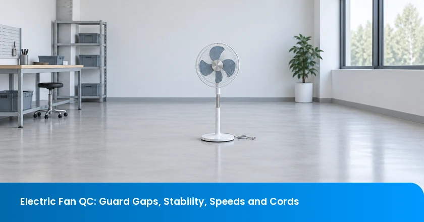
Electric fan quality control (QC) should examine the assembled guard, base, speed functions and power cord in the configurations the product is designed to use. A fan that stands upright and spins is not necessarily ready for shipment. Check protection from the blade, the specified stability conditions, actual control responses and the cord path during permitted movement. Record unperformed safety or performance tests separately so a tidy appearance does not conceal missing evidence.
What the Inspection Must Establish
- The guard is correctly assembled, and required access checks have the right method and result.
- The base and adjustments are assessed in the configurations specified for stability.
- Speed, oscillation and other controls produce the intended responses.
- The cord remains correctly routed without unsafe tension, trapping or abrasion.
Define the Fan Type and Applicable Test Scope
Identify the fan before choosing its checks. Table, pedestal, tower, ceiling and ventilation fans have different assemblies and installation conditions. This checklist concentrates on household table and pedestal fans, with relevant observations for other designs only where their specification supports them. A heater-fan combination or an installed ceiling fan needs additional, product-specific planning.
IEC 60335-2-80:2024 covers the safety of household and similar electric fans and also applies to separate controls supplied with them. The published scope includes types such as table and pedestal fans. Use the applicable product requirements and national adoption for the destination; the IEC publication alone does not establish the market’s legal route or certify the shipment.
The responsible technical specialist should identify the required standard editions, test procedures and supporting reports. Public standard descriptions explain scope, but they do not provide the complete methods. Agree which observations can be made during factory inspection and which checks require qualified electrical personnel, controlled apparatus or laboratory assessment. Keep model and revision references consistent between those records and the supplied goods.
Prepare the Assembly and Operating References
Before appointing a provider, review its organization and then confirm the practical scope of the proposed visit. Available equipment, access to assembled samples and the time required for the agreed checks matter as much as the general service category. Start the organizational review with TradeAider’s company background.
Supply the approved guard, blade, base, controls and cord-routing references for the exact model. Include assembly instructions, component revisions, the permitted height and tilt positions, and the intended oscillation behavior. These references allow the inspector to compare a finished fan with its controlled design rather than another unit that may share the same assembly error.
Specify the electrical supply and operating modes, then identify the required observations and acceptance criteria. Where a numerical result is requested, state the method and instrument needs. Do not leave a factory operator to invent a guard-gap limit, stability angle or acoustic threshold on the day of inspection.
Make adjustment and test sequences explicit. Initial checks should establish that the fan is assembled and safe to operate before functional observation begins. Record any disassembly, adjustment or repair, since a later photograph may no longer show the delivered condition. Keep the sample identifier visible in the associated records so the reviewer can reconstruct what changed.
Electric Fan Inspection Checklist: What to Record
Give guard access, stability, speed functions and cord condition distinct entries in the report. Each entry should identify the sample, configuration, reference and result. Where a required procedure is not completed, name the missing evidence and the reason. A single “running normally” statement cannot answer all four questions.
| Inspection area | Compare or observe | Record | Unresolved finding |
|---|---|---|---|
| Guard and blade access | Guard assembly, openings, retention and required access method | Location, configuration and specified probe result | Missing fixing, distortion or unverified access protection |
| Stability and support | Base parts, height/tilt locks and prescribed stability setup | Assembly state, surface or fixture and result | Loose support or missing configuration coverage |
| Speed and controls | Startup, selectable speeds, stop and other specified modes | Command and actual response under defined supply | Indicator changes without the intended function |
| Oscillation and sound | Travel, abnormal vibration, rubbing and specified acoustic check | Operating state, symptom and measurement conditions | Interference, stalling or unsuitable noise setup |
| Power cord and plug | Identification, damage, routing and strain-relief arrangement | Rest and permitted-movement observations | Tension, trapping, abrasion or electrical concern |
Use an overall image to locate the feature, followed by a closer view that shows the actual finding. For movement-related problems, identify the starting and ending positions. A close-up of an undamaged cord gives little information if the suspected problem occurs only when the head turns away from center.
TradeAider’s inspection-standard guidance provides a basis for discussing inspection criteria and defect reporting. Add the fan-specific test references and configuration plan to it. The buyer needs to know whether an entry describes an appearance discrepancy, a failed criterion or a scope limitation, because those findings require different follow-up decisions.
Guard Gaps: Check Access to the Blade, Not Just Spacing
Guard gaps are part of blade-access protection, but measuring an opening is not the same as establishing whether a hazardous part can be reached. Examine the complete protective assembly: front and rear guards, the joining ring or clips, screws, ribs and any openings created by incorrect assembly or distortion.
IEC 61032:1997 specifies test probes used to verify enclosure protection, including protection against access to hazardous parts. The applicable fan safety method determines which probe, conditions and assessment are relevant. Its public scope is not a universal fan-gap specification. A ruler measurement can document a dimension; it cannot replace the required access verification.
Inspect for missing clips, incomplete engagement, broken wires or ribs, loose fasteners and a guard fitted in the wrong orientation. Check the intended blade clearance and record any rubbing or interference observed under the approved procedure. A guard may have the expected nominal openings yet sit too close to the rotating assembly because it is bent or incorrectly secured.
Use the specified equipment and authorized method for access checks. Never insert fingers, improvised objects or tools into a running fan. If the guard is damaged or insecure, keep the unit out of functional operation until the condition has been assessed. Do not remove a guard to obtain a favorable running result and then report the fan as inspected in its supplied state.
When a guard is corrected or replaced, confirm both its retention and the required protective function. A cosmetic straightening operation may change clearance or attachment geometry. The technical owner should decide whether the correction calls for renewed access checks or other reassessment before acceptance.
Stability: Verify the Base in the Required Configurations
A fan standing on a level bench provides an initial observation, not the result of the specified stability method. Height, head tilt, base assembly and cord position can change the configuration being assessed. Cover the states required by the approved procedure rather than assuming that one upright position represents every permitted use.
Start with the support assembly. Compare the base, feet, column, fasteners and locking parts with the drawing and packed components. Verify that the correct parts are fully seated and that adjustment locks hold as specified. Missing base hardware can be hidden by a fan’s weight while it remains undisturbed on the inspection surface.
Record the height and tilt setting for each required check, along with the prescribed surface or fixture. Use the specified method for any inclination, force or operating condition; there is no single improvised push that establishes conformity for all fans. The purpose of the record is to make the result reproducible, not merely to photograph a fan that has not fallen over.
During permitted operation, observe abnormal rocking, movement or vibration and identify the supporting surface. Separate an uneven bench from looseness in the fan, while retaining the original observation. Do not tape the base down, wedge a foot or reduce the approved height to conceal a finding.
If the method or fixture is unavailable, state which stability evidence is missing. A buyer can arrange the proper assessment without misclassifying the absence as a tested failure. Conversely, an actual failed criterion should not be relabelled as a setup limitation merely because the unit looks acceptable in a less demanding position.
Speed Functions: Separate Control Response from Airflow Performance
Check what each control does to the fan, not only what appears on a display. Record startup, each specified speed selection and the stop function under the required supply conditions. Identify modes that intentionally vary speed so their programmed changes are not confused with erratic operation.
IEC 60879:2019+AMD1:2025 addresses performance-measuring methods for comfort fans and regulators, including conventional, tower and bladeless designs within its stated scope. That scope includes a rated power input below 125 W and explicitly excludes fan safety. Confirm applicability before selecting a method. A safety report, a spinning blade and a performance measurement answer different questions.
A visible speed change supports a functional observation, but it does not establish the declared air delivery. If speed or airflow measurements are required, use the agreed method, setup and suitable instrument. Record the mode and conditions with the reading. Holding a strip of paper in front of the guard may show moving air, but it is not a rated airflow test.
TradeAider’s pre-shipment inspection service is conducted when the order quantity is 100% complete and at least 80% packed for export. Pre-shipment inspection (PSI) includes agreed finished-goods functional, measurement and packaging checks. Discuss the fan-specific equipment and duration in advance; that service scope does not imply that every laboratory performance or safety test is available during a factory visit.
Preserve distinctions in the report: a command that is ignored, a function that responds incorrectly and a requested rating that was not measured need separate entries. This helps the buyer ask for the right correction or additional evidence rather than accepting a broad control-panel photograph as the result.
Oscillation and Noise: Observe the Fan Through Its Travel
Observe oscillation over the travel specified for the model. Watch for hesitation, interference, unusual vibration and contact between moving and fixed parts. Compare the commanded oscillation state with the actual movement. Do not force a head or linkage beyond its permitted range to create a test condition.
Separate abnormal-sound observations from a numerical acoustic claim. IEC 60704-2-7:2020 provides a fan-specific airborne acoustic test code for household and similar use. Its scope excludes several categories, including fans with additional heating or humidifying functions. Follow the applicable full method and its referenced requirements; the public description does not establish a universal acceptable noise level.
For an agreed acoustic measurement, record the instrument, operating mode, measurement position and background conditions. If the factory environment masks a quiet-operation rating, retain the limitation and arrange a suitable setting. A recording of a rattle can help locate a fault, but it should not be presented as proof of a sound-power or sound-pressure claim.
Note when a symptom occurs: startup, one speed, one direction of travel or a particular height. That timing can help the technical reviewer distinguish loose trim, blade contact and a movement-related assembly issue. Stop operation if rubbing, instability or another unsafe condition appears; do not continue simply to demonstrate that the symptom repeats.
Once stopped and safely isolated, retain the configuration for examination where practical. Adjusting the head back to center before documenting the finding can remove the very condition that explains it.
Cord Inspection: Look for Tension, Trapping and Abrasion
Cord inspection should follow the cable path through permitted motion. In the June 2004 SMC oscillating-fan recall, oscillation could damage the electric power cord, leading to a short circuit and possible ignition of the plastic case. This specific historical mechanism shows why an intact-looking cord at rest does not establish that its routing remains appropriate as the fan moves.
Check the plug and cord identification against the approved destination specification. Look for cuts, crushed insulation, damaged pins, loose or incorrect parts and an unsuitable cable entry. Compare strain-relief components, grommets and routing clips with the controlled assembly. Visual inspection does not establish conductor size, electrical continuity or the performance of the anchorage under a specified test.
Follow the approved sequence from the rest position through the required height and tilt settings, then permitted oscillation. Watch for loss of slack, trapping and contact with edges or moving joints. Make manual adjustments only in the safe state required by the instructions. If the cable tightens or catches, stop and document the condition rather than repeatedly flexing it to see whether it fails.
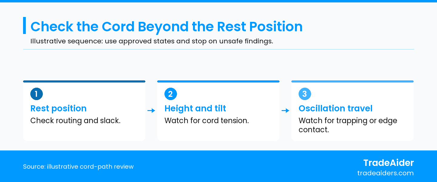
Illustrative inspection sequence. Use the approved procedure and stop if unsafe tension, trapping or contact appears.
Any required anchorage, flexing or electrical test needs its defined method and qualified execution. Do not improvise a pull load or open an energized housing. Repairs should follow technical approval and be checked against the original routing and protective requirements, not merely covered with tape.
An acceptance quality limit (AQL) plan can support agreed workmanship sampling; use the AQL calculator for that calculation. Keep cord safety concerns and missing test evidence outside any assumption that an acceptable cosmetic defect count settles them. Traceability may help isolate changed goods, but the release decision still needs valid evidence for each proposed group.
Illustrative Example: A Late Cord-Routing Change
Consider an illustrative example involving 1,200 pedestal fans. Finished, packed goods and production records are available. A late routing-clip change affects the final 240 units, while the earlier 960 remain separately identifiable through verified production and carton records. The changed routing looks slack with the head centered, but at an approved travel extreme the cord pulls tight against a pivot edge. No damaged insulation or injury is assumed; this is not a TradeAider client case.
The buyer holds the 240 changed fans for correction. The centered appearance did not cover the configuration that exposed the routing problem. The earlier 960 can be considered separately only if their baseline checks remain valid, segregation is verified and all other release requirements are satisfied. Subtracting 240 from 1,200 establishes a count, not evidence that the remaining fans are acceptable.
The technical owner approves the corrected routing, and the factory reworks the affected 240 while preserving their identities. Verification checks the approved cord path over the required height, tilt and oscillation states, followed by any electrical or durability reassessment the correction requires. A photograph at rest is useful as part of that record, but it does not close the movement-related finding.
This illustrative example depends on reliable segregation. If the records cannot establish which units received the change, the hold must expand beyond 240 until the affected scope is resolved. No automatic release of the 960 is implied, and no universal angle, test duration or cycle count is created by the example.
Build a Fan Inspection Request Around the Open Decisions
Send the fan model, destination and controlled assembly revision, including the guard, base, cord path and supplied controls. List the required operating and adjustment states, test methods, acceptance criteria and relevant technical reports. Highlight any recent component or assembly change so it can be traced to the finished goods.
Add the order quantity, packing status, access arrangements and open findings. Ask the inspection team to confirm the feasible factory scope and any separate test arrangements. Request sample-linked construction, functional, measurement and packaging observations with photographs and clear limitations. Those records should let you assign a correction, commission missing verification or make a documented shipment decision.
To arrange that scope, Contact TradeAider to plan your electric fan inspection.
Frequently Asked Questions
Should a flat-packed fan be inspected after assembly?
Yes. Use the supplied parts and approved assembly instructions to check the finished configuration. Confirm that the consumer receives the correct fasteners and usable instructions as well as compatible components. A satisfactory loose base or guard does not establish the completed assembly, and borrowed factory hardware can hide a missing item in the retail pack.
Can an extension cord be used during the inspection?
Use the specified supply arrangement; an unapproved extension can change the conditions or add a separate fault. Confirm the voltage, frequency and connection required by the method and product instructions. If additional supply equipment is necessary, have the responsible personnel approve it and record the arrangement so the result can be interpreted correctly.
Does an intact carton prove the fan guard survived transport?
No. Packaging appearance does not establish the condition of the guard inside. Inspect selected unpacked goods for distortion, loose retention parts and blade clearance under the approved plan. If transport performance is a requirement, use its defined packaging test and subsequent product checks rather than treating the exterior carton condition as a substitute.
Do remote controls and timers need their own checks?
Yes, when they form part of the approved product specification. Identify the intended commands, timer behavior, supplied batteries or accessories and any required response after power interruption. A working local speed switch does not establish those additional functions. Record the control used and the actual response, including any connection or setup limitation affecting the check.
Related Articles

Grow your business with TradeAider Service
Click the button below to directly enter the TradeAider Service System. The simple steps from booking and payment to receiving reports are easy to operate.