
For USB-C cables covered by Regulation (EU) 2025/2052, EU importers should connect three things before approving a model: the required cable class, the power text on both plugs, and technical evidence for that same assembly. A printed 240W mark does not prove electrical performance. Equally, one combined voltage-drop reading does not establish that both the power and ground paths meet their separate requirements. Start with the cable’s actual connectors, length, construction and supported capability, then match its artwork and test records to the version being purchased.
Regulatory position checked: October 30, 2026. Covered USB Type-C cables need model-specific markings and supporting evidence. The wider rules for external power supplies and wireless charging products require separate assessments.
Three checks before approving cable evidence
- Identify the covered C-to-C assembly and the specification version used to assess it.
- Verify the correct power text and character heights on both plug overmoulds.
- Read VBUS and ground results separately, then confirm that the report covers the ordered model and revision.
Start with the cable assembly covered by the rule
Regulation (EU) 2025/2052 defines a USB Type-C cable as an assembly with USB Type-C plugs and overmoulds at both ends, rated either 60W or 240W, meeting the USB Type-C Cable and Connector Specification, Release 2.4, October 2024. Annex II point 3(f) requires cables placed on the market with USB Type-C plugs at both ends to be USB Type-C cables. Read the legal cable definition.
The both-ends condition matters. Photograph and identify both connectors rather than accepting “USB-C cable” as a complete supplier description. A USB-A-to-C cable or a lead fixed to another product is a different configuration; this particular C-to-C definition does not settle every rule that may apply to those products. A bundle with a charger also does not remove the need to identify the cable itself.
The European Commission’s dedicated product guidance explains that the measure brings USB-C cables into ecodesign requirements addressing supported power markings and electrical losses. The practical purchasing question is therefore broader than whether the cable can charge one demonstration device. Ask which assembly, rating and specification requirements the supplier actually assessed.
Freeze a model description covering connector types, length, conductor and contact design, any electronic identification, and the claimed power and data capabilities. Define whether multiple lengths or variants are separate records or are supported by a documented technical assessment. A catalogue photograph showing the same outer braid cannot resolve those differences.
Use that description as the reference for subsequent order checks. TradeAider’s inspection standards give the inspection context; the buyer and technical owner should still agree the exact cable model, drawings, artwork and checks required for the shipment.
Check the power text on both plug overmoulds
Annex II point 5(e) requires the text 60W or 240W on the overmoulds of both plugs, according to maximum supported power. The digits must be at least 1.2 mm high and the letter W at least 0.6 mm high. Point 5(f) requires the information to be clearly visible, legible and indelible. Annex II marking requirements.
The overmould is the molded housing around the plug. A packaging statement or a label on only one end does not substitute for the required text on both plug overmoulds. The legal marking should reflect the supported capability, rather than the wattage of a charger with which the cable happens to be bundled.
| Check on the actual cable | Reference to agree | Action if it does not match |
|---|---|---|
| Power text on each plug overmould | 60W or 240W, according to maximum supported power | Request corrected artwork or investigate unsupported capability; do not simply select the larger number. |
| Height of the digits | At least 1.2 mm for 60 or 240 | Check the actual produced mark, not only a scaled drawing or packaging mock-up. |
| Height of the W | At least 0.6 mm | Measure the letter independently from the digits where their sizes differ. |
| Visibility, legibility and permanence | Approved marking method and relevant verification evidence | Record unclear or removable markings and agree how the issue will be corrected and verified. |
| Both ends and current revision | Approved photographs/drawings for each plug housing | Identify which model or production version is affected by a mismatch. |
Keep statutory power text separate from USB-IF certification artwork. The USB-IF logo-license requirements govern commercial use of its licensed logos and their relationship to certified products. When a supplier proposes a combined power/data logo, request the applicable authorization and approved artwork rather than assuming a statutory wattage-text requirement grants permission to use every USB logo.
Likewise, the regulation’s Common Charger logo concerns qualifying interoperable external power supplies; it is not the cable’s 60W/240W text. Check that the supplier has not copied an adapter badge into the cable artwork. Keep the cable marking approval tied to the capability evidence so that an artwork change cannot quietly turn an unsupported cable into an apparently higher-rated product.
Read cable-loss evidence at the correct electrical boundary
Section 4.4.1 of USB Type-C Release 2.4 limits cable IR drop to 500 mV for VBUS and 250 mV for ground at the cable’s maximum rated VBUS current capacity. The boundary includes the contact resistance of the mated plugs and receptacles at both ends; the ground requirement also accounts for additional VCONN return current when VCONN is supplied. USB Type-C 2.4 official specification archive.
IR drop is the voltage lost when current flows through electrical resistance. VBUS is the USB power path, while ground provides the return path. VCONN supplies certain cable electronics. These distinctions affect what the test includes: a measurement of conductor wire alone cannot stand in for the specified assembly boundary with its mated contacts.
| Evidence item | What the result must identify | Interpretation |
|---|---|---|
| VBUS path drop | Measured mV, rated test current and the full defined contact/cable boundary | Assess against the 500 mV requirement for that path. |
| Ground-path drop | Measured mV, rated VBUS current and any additional VCONN return current | Assess against the 250 mV requirement with the applicable return-current conditions. |
| Fixture and contacts | Mated plug/receptacle arrangement and how contact resistance is included | Resolve a different boundary before accepting an unexplained low resistance or drop value. |
| Cable configuration | Model, length, construction and electronic/powered-cable arrangement | Confirm that the tested assembly represents the model being purchased. |
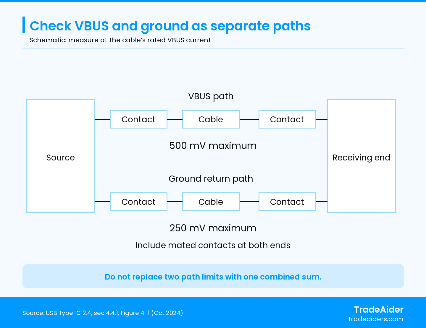
Assess VBUS and ground separately at the cable’s maximum rated VBUS current. Include the mated contact resistance at both ends; account for additional VCONN return current where applicable. This schematic does not replace the complete test method.
Illustrative example: A matched cable report records 540 mV on VBUS and 120 mV on ground at the cable’s rated 3 A VBUS current, using the applicable contact boundary. Adding the readings gives 660 mV, but that sum does not clear the two path requirements: the VBUS result exceeds 500 mV even though the ground result is below 250 mV. This is a hypothetical explanation, not a TradeAider test result.
The technical owner should address the VBUS finding and determine the appropriate corrective and verification work. If the report omits the current, fixture or contact boundary instead, the immediate action is clarification or a suitable test, rather than declaring a complete model pass or failure from an uninterpretable number. Powered-cable configurations also need the applicable method provisions; the simplified example is not a complete test plan.
Do not borrow the standardized cable-resistance correction used in the regulation’s EPS output measurement method as a standalone cable acceptance limit. That correction serves an EPS measurement model; the cable’s own requirements and test boundary still need assessment. Similarly, an AQL calculator can help plan order sampling but cannot establish the model’s electrical compliance.
Keep power, data and certification claims distinct
The USB-IF cable certification program distinguishes cable capabilities. Its program requires 60W or 240W power markings and, except for High-Speed USB 2.0 USB-C to USB-C cables, the appropriate supported data-rate marking. USB-IF cable certification requirements.
A wattage mark is not a data-speed claim. Request the claimed data class separately and check any combined artwork against the actual cable record. Do not infer high-speed data capability merely because a cable supports a higher power class, or assume two cables with the same exterior perform the same functions.
Electronic marking is another layer of evidence. Release 2.4 requires all full-featured Type-C cable assemblies to be electronically marked; for USB 2.0 Type-C assemblies, its requirement applies when rated above 3 A. Extended Power Range cables have additional electronic-identification requirements. Ask the technical reviewer to identify the applicable cable category and the recorded identity data, rather than applying one e-marker rule to every cable.
An e-marker is electronic identification within the cable assembly. Its reported identity and capability data should be consistent with the physical construction and claimed class, but reading that identity is not the same as measuring electrical performance. An external 240W mark, electronic capability data and a path-drop report each answer a different question.
The USB-IF EU-conformity guidance identifies the Type-C Release 2.4 reference associated with the EPS regulation and explains its cable/connector program route. Keep the specific edition and test scope in the supplier file. If a report uses another edition or only a different EU product regime, ask the technical owner to map its coverage to the requirements relevant here. Do not treat a certificate title alone as that mapping.
Build a model-specific supplier evidence request
Annex II point 6(j) requires documentation demonstrating USB Type-C cable compliance with point 3(f); Article 4 also addresses the applicable technical documentation and equivalent-model identifiers. Technical-documentation provisions.
Separate the manufacturer’s technical assessment, any laboratory or certification-program record, and the order-inspection report. Identify who is responsible for each conclusion and what evidence the overseas buyer actually needs.
Send the following request with the cable specification. The response fields are intended for actual file names, model identifiers and revisions, not an unqualified “compliant” entry. Where the supplier does not have an answer, keep the missing evidence visible and assign it to the relevant engineering or documentation owner.
| Supplier response field | Evidence to enter | Buyer decision supported |
|---|---|---|
| Cable identity | Manufacturer:___; model/revision:___; connector types:___; length:___; construction:___ | Whether this is the assembly named in the report and order. |
| Claimed class | Power rating:___; data class:___; electronic identity and applicable category:___ | Whether the claimed capabilities and required marking are consistent. |
| Both-plug artwork | Drawing/photo versions:___; digit and W heights:___; marking process:___ | Whether the actual two overmoulds meet the approved marking requirements. |
| Electrical evidence | Report/method/edition:___; rated current:___; VBUS result:___; ground result:___; contact and VCONN conditions:___ | Whether the results can be interpreted for the relevant paths and configuration. |
| Variant coverage | Covered IDs and lengths:___; technical differences:___; assessment or identity basis:___ | Whether the evidence legitimately extends to the purchased variant. |
| Current order handoff | PO/SKUs:___; approved references:___; revision/change record:___; intended report recipient:___ | Whether shipment observations can be matched to the controlled model file. |
The required document set is not automatically a universal third-party certification package. Ask the responsible economic operator to identify the applicable conformity-assessment route and retain the supporting records. USB-IF testing or listing may provide useful evidence within its stated scope, but it does not remove responsibility for the complete applicable legal assessment.
If a supplier offers one report for several lengths or part numbers, request the technical coverage basis. A longer cable, different contact supplier or changed electronic identification may affect relevant requirements. Conversely, do not demand retesting solely because a retail code changed when properly supported identity or equivalence evidence already resolves the difference.
Carry those records into the purchased order
A supplier report must be matched to the purchased cable’s relevant configuration before the buyer relies on it; a shared retail name or wattage claim does not explain differences in length, conductor construction, connectors or electronic identification.
Schedule pre-shipment inspection against the approved model and marking references, rather than asking only for a generic USB-C cable check. For PSI, the order quantity should be 100% complete and at least 80% packed for export. The latter threshold concerns packing, not production completion. Allow time to investigate discrepancies and verify corrections before the buyer’s shipment decision.
Use a change record when the supplier alters length, conductors, plug housings, contact materials, electronic identification, markings or assembly process. Ask the technical owner which existing conclusions remain valid and which require additional evidence. A new jacket color need not be treated as equivalent to an electrical redesign, but its actual effect should be understood rather than guessed.
The EUR-Lex summary states that the regulation generally applies from December 14, 2028. Plan model selection, artwork approval and evidence closure accordingly. Do not assume an EPS-specific transition automatically extends to a cable; the responsible compliance owner should resolve the applicable obligations and timing for the actual product.
During the order check, identify mixed models or revisions through the actual cable and package references. If one plug housing has the wrong power text or a substituted model appears, record photographs and the affected SKUs and quantities. Ask the buyer whether those goods should be held while the supplier and technical owner determine the correction and its implications.
A packaging correction cannot resolve an unsupported cable capability. After any approved correction, retain the supporting evidence and arrange the necessary reinspection or technical testing for the changed issue. Keep the observed shipment discrepancy separate from the scope of any model-level electrical conclusion.
Define the inspection and technical-review handoff
An order inspection can check agreed visible features and perform agreed checks with suitable references and equipment, but it does not by itself replace technical conformity assessment of the cable model.
Agreed observable checks can include the identity of both connectors, length, supplied model/variant, text on each overmould, marking dimensions, visible consistency and packing references. Electrical or electronic-identification checks require a defined method and suitable equipment; their availability and scope should be agreed before the inspection visit. A general inspection booking does not establish that every specification test can be performed on site.
The report should distinguish what was observed, what was measured, the references used and what could not be completed. If markings appear correct but the matching technical file is unavailable, record that gap explicitly. If the provided report covers a different cable length or construction, describe the mismatch instead of silently borrowing its conclusion for the current goods.
Confirm the report recipient, intended use, language, format and any institution requirements before booking. For a small importer or purchasing agent, the product and order information already available can start that discussion; outstanding technical references should be resolved during scope preparation. Agree who can accept a limitation or authorize further review, so a pending item is not mistaken for a completed test.
Send TradeAider the available cable specifications and order details, factory, destination, intended timing and known marking or evidence concerns. Identify the report user and any acceptance requirements. Contact our team to discuss a suitable inspection scope and a report of the agreed checks, observed findings and limitations.
FAQ
Does a 240W marking guarantee every device will receive 240W?
No. A cable power rating describes its supported capability, while actual delivered power also depends on the source, receiving device and their operating arrangement. Treat 240W as a cable capability claim to substantiate, not a promise about every charging combination. Check the cable’s class and evidence separately from the power available from a particular charger or accepted by a particular device.
Can a 100 W cable simply be relabeled as 240W?
No. A new printed number cannot establish that the cable construction and electronic identification satisfy the requirements for its claimed class. Ask for the applicable specification assessment and technical evidence before approving a changed rating. A supplier’s previous 100 W description is a reason to investigate the actual design and coverage, rather than either accepting a relabeling or assuming the old file proves the new claim.
Does USB-IF certification replace the complete EU conformity file?
No. USB-IF records can support their stated test scope, while the responsible economic operator still needs the applicable EU conformity assessment and documentation. Confirm the product identity, program, specification version and covered requirements in the record. A valid result for one aspect should remain useful evidence, but it should not be presented as a blanket conclusion about every legal duty or shipment.
Related Articles


Grow your business with TradeAider Service
Click the button below to directly enter the TradeAider Service System. The simple steps from booking and payment to receiving reports are easy to operate.