
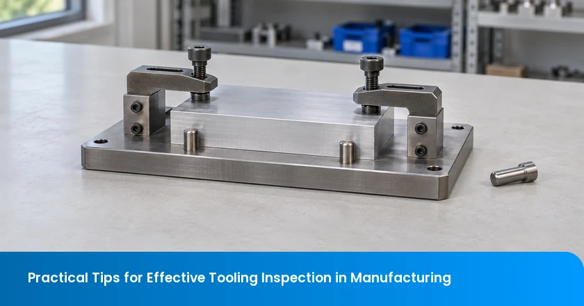
Effective tooling inspection starts with the approved tool configuration and the features that control the workpiece. Check condition, locating surfaces, clamping and relevant dimensions using suitable methods, then record findings against defined criteria. Follow a change or repair with targeted verification before returning the tooling to use. This approach connects the tool's condition with the production decision it must support.
For a manufacturing team, the immediate question may be whether a fixture can start the next run. An importer may need to understand why dimensions have shifted between batches. Both need identifiable tooling, reliable observations and a clear next action.
Make Each Tooling Check Support a Decision
- Identify the approved tooling and product revisions before choosing inspection methods.
- Inspect contact surfaces, wear and restraint using an approved safe procedure.
- Record actual values with units and criteria, keeping missing requirements pending.
- Verify affected setup and output after relevant changes before authorized reuse.
Define what the tooling inspection must establish
Identify the tooling, product and drawing revisions, intended function, critical interfaces and inspection decision before selecting instruments. Tooling can include a machining fixture, drilling jig, forming die or assembly aid. A routine condition check and acceptance of a repaired tool answer different questions, so their scope should be explicit.
Break an assembly into the components that locate, support and hold the workpiece. Jergens' fixturing range distinguishes workholding from locating components and lists pins, keys, bushings, supports and clamps. These categories help you identify what each inspection item should address. Jergens fixturing components.
A locator establishes position relative to a reference. A support carries the part, and a clamp restrains it. A datum is a reference used to define geometry on the drawing. Mark the relevant contact points on a photo or sketch so the inspector can connect the tooling feature with the product characteristic it influences.
Gather the approved assembly reference, component specifications, loading sequence and previous findings. Establish whether the check covers initial setup, routine use, a repair or an investigation. Missing design information becomes an assigned technical question before anyone invents a tolerance.
Inspect condition, seating and clamping safely
Plan hands-on checks and maintenance around safe access. HSE guidance emphasizes competent people, manufacturer instructions and isolation of equipment, including stored energy. Its legal references concern the UK. The practical hazards of unexpected movement, pressure and unsupported parts need assessment in the actual workplace. HSE equipment-maintenance guidance.
Use the site's approved isolation and verification procedure before entering hazardous areas or cleaning, adjusting or dismantling tooling. An energized functional trial needs its own assessed method and appropriate protection. Stop the activity if the necessary access or controls are unavailable.
Inspect cleaned locating and support surfaces, pins, bushings, fasteners and clamps against the approved reference. Look for trapped chips, dents, corrosion, looseness and wear at the actual contact points. Record the location and observed condition before cleaning or repair changes the evidence. Use the manufacturer's cleaning method.
Check how a representative workpiece seats under the approved loading sequence. Observe contact, rocking, interference and orientation. If seating changes between loads, investigate the cause before tightening the clamp to force the part into position. Keep observations separate from conclusions about the part or tool.
Examine clamp pads, joints, locking features and clearances. For powered workholding, include the specified hoses, connections and operating conditions within the competent person's scope. Compare adjustment or pressure settings with the approved setup. A handle reaching its end position alone gives limited evidence about how the part is restrained.
Make photographs specific enough to repeat the observation. Include the tool identifier, an overall view and a close view of the finding. Label the contact or feature in the record. A photograph of an unidentified scratch cannot show which surface was affected or whether the inspection covered the working position.
Measure the features that control the process
Select dimensions from the tooling function and approved drawing. Record actual values, units, method, instrument and limits alongside the tooling revision. Relevant features might include a locating-pin diameter, bushing position, support height or alignment. The responsible engineer should define the features and criteria for that tool.
A caliper may suit an accessible dimensional check. A micrometer may suit a specified external diameter, while an indicator can reveal movement during a defined seating or alignment trial. A go/no-go gauge answers a specified acceptance question without supplying an actual dimension. Access, contact geometry and demonstrated measurement capability determine suitability.
Check instrument identification, calibration status and the applicable range. Perform the required pre-use checks, such as checking clean contacts, zero and a suitable reference. These checks complement the calibration program. They help detect a problem introduced during handling or use.
Metrological traceability concerns a measurement result. NIST describes its connection to a reference through a documented chain of calibrations, with measurement uncertainty contributing along that chain. Keep the method and relevant calibration records connected to the reported result. NIST metrological traceability guidance.
NIST also explains that traceability alone does not establish fitness for a particular measurement need. Consider uncertainty, method and conditions when judging a result near its limit. Refer unresolved measurement questions to the technical reviewer instead of repeatedly measuring until a favorable value appears. NIST guidance on fitness for purpose.
Preserve the drawing's metric or inch units throughout the record. Check unit settings before use and retain the original value when an approved conversion is needed. Document relevant temperature, cleanliness, restraint and setup conditions. A difference between readings deserves investigation if the methods or conditions changed.
Choose manual and automated methods by the task
Choose visual, contact and automated methods for the feature, access and decision you need. An analog dial can show movement during a setup check. A digital instrument can simplify reading and transfer values into a record. Compare their actual capability and operating conditions before assigning either to an acceptance task.
Begin visible-condition checks with suitable lighting and access. Magnification can help examine a small surface feature, but the observation remains limited to what the method can reveal. Suspected subsurface damage requires a separately selected examination. Avoid describing an ordinary visual check as proof that the tooling has no hidden flaws.
Automation can support repeated inspections when the part presentation, lighting, sensing and software are suitable. Establish the covered features, accepted reference conditions and handling of uncertain results. Challenge the arrangement with representative conditions before relying on it. Retain the program and setup version with the inspection record.
A specific NIST M48 vision-system study describes limitations related to camera resolution and illumination, then validation with check standards and reference materials. It illustrates why system changes need evidence. Its laboratory capabilities are specific to that particular machine and its artifacts. NIST M48 validation abstract.
When the task includes selecting a separate measurement fixture, evaluate restraint and measurement access with representative parts. Record the approved configuration and loading method. Routine production-tooling inspection then checks the arrangement as used. A trial performed with different supports or clamping conditions needs review before its results can be compared.
Use a tooling inspection record that leads to action
Use the record below with the tool's approved drawing and instructions. Enter actual observations or measurements and the applicable criterion. Mark an item pending when a missing requirement prevents judgment, and name the engineer or tooling owner who must resolve it. Record a justified disposition for items outside the defined scope.
| Check | Complete during inspection | Decision and follow-up |
|---|---|---|
| Identity and scope | Tool ID ___ Product/revision ___ Drawing/revision ___ Reason/date ___ | Confirm the record covers the installed configuration. |
| Safe access | Approved procedure ___ Access/energy condition ___ Responsible person ___ | Stop if the required safe method is unavailable. |
| Seating and locating | Contact/feature ___ Condition ___ Reference ___ Photo ___ | Investigate contamination, rocking, interference or wear. |
| Clamping and movement | Clamp/setting ___ Trial condition ___ Observation ___ | Refer changed restraint or abnormal movement for review. |
| Critical dimensions | Feature ___ Limit/unit ___ Actual/unit ___ Instrument/method ___ | Apply agreed criteria. Missing limits remain pending. |
| Condition and maintenance | Wear/damage ___ History ___ Required action ___ | Identify affected use, repair owner and recheck scope. |
| Disposition and output | Accept/hold/pending ___ Affected output ___ Follow-up owner/date ___ | Record verification and authorized return to use. |
Keep each measured feature on its own continuation line when several dimensions are involved. Reference the relevant drawing location and retain the raw readings. A general “dimensions OK” entry makes a later investigation difficult because it hides what was actually measured.
Connect a tooling finding to the product run, shift or time window it could affect. The factory's quality owner can then assess the relevant output and decide its disposition. Tool repair and product disposition need identifiable evidence even when the same team coordinates both activities.
For an order already in production, TradeAider's during production inspection can address agreed product observations and dimensional checks. Share the tooling concern to help focus the feasible checks on affected characteristics. Keep the tooling engineer's repair decision and the product-inspection findings identifiable in the follow-up.
Illustrative example. A locating pin is replaced
Assume a factory replaces a locating pin on a drilling fixture and notices changed hole positions on first-off parts. This is a hypothetical example. Enter the fixture identity, replaced component, product revision and reason for inspection in the record. Hold the fixture for the affected task while the tooling engineer reviews the replacement and setup.
Using the approved safe procedure, the team records the pin's identification, fit, seating and support condition. It preserves the first-off results and photos. Finding debris at a contact point gives the team an observable condition to investigate. It does not establish that debris explains every positional change.
If the available drawing lacks the required positional criterion, enter “pending” against that feature and assign the design owner to provide the controlled requirement. A new pin matching the old pin's measured diameter does not resolve a missing hole-position requirement. The product decision waits for the necessary reference and evaluation.
After the authorized correction, repeat the affected setup checks and inspect representative output using the agreed method and criteria. Record whether the evidence resolves the original finding and who authorizes return to use. Retain any remaining discrepancy for investigation. This example specifies a decision path, without inventing a tolerance, sample size or successful client outcome.
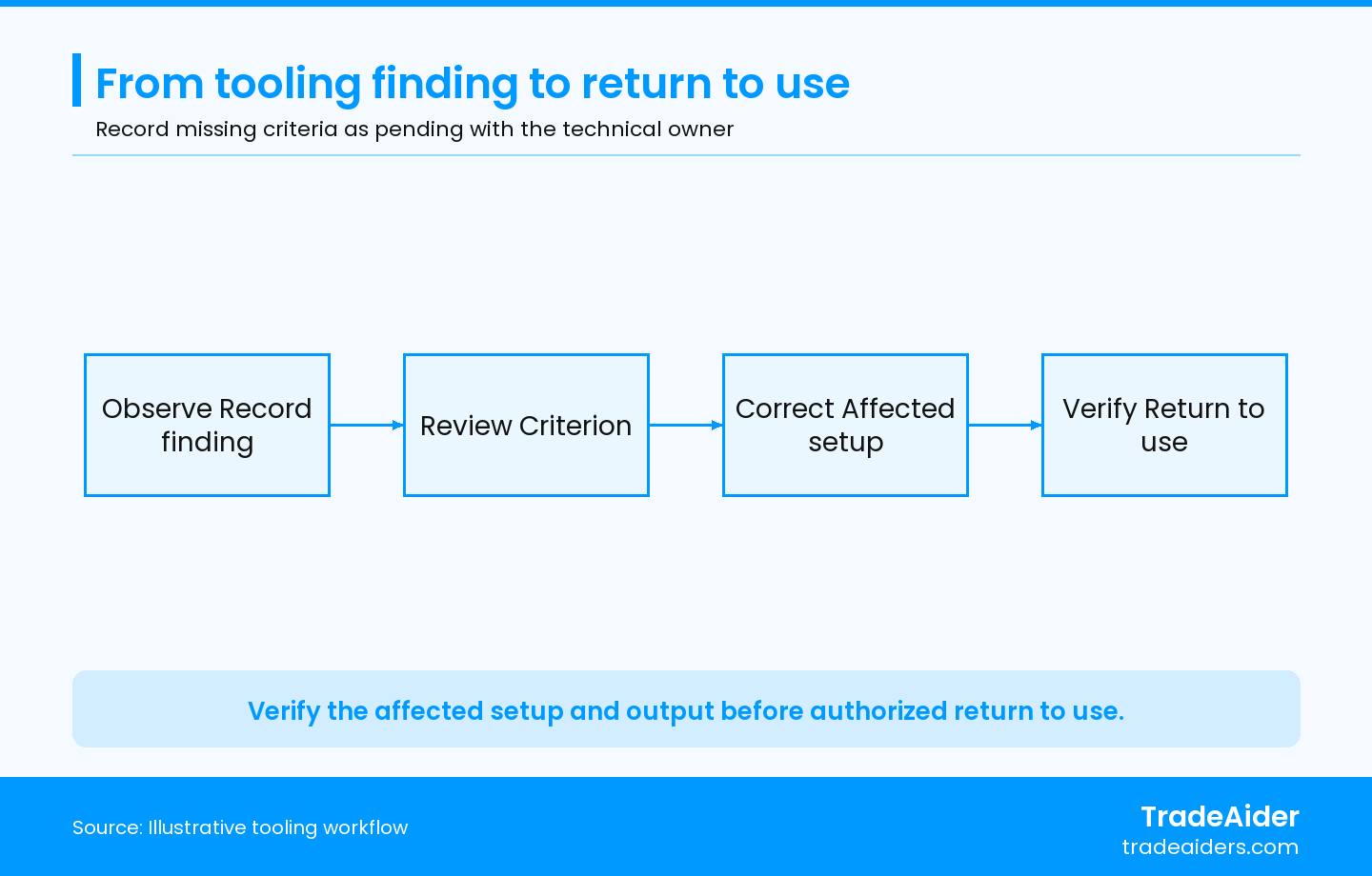
Illustrative inspection workflow. A missing criterion stays pending with the technical owner before a pass decision.
Set maintenance and reinspection triggers
NIST does not generally require or recommend a fixed recalibration interval. Requirements, instrument stability and environment influence the appropriate interval. Use these considerations with the actual instrument's history and applicable obligations when establishing its program. NIST calibration-interval guidance.
Tool maintenance has its own basis. Use the tooling manufacturer's instructions and the factory's engineering assessment to identify cleaning, lubrication, wear and replacement needs. A locating component, cutting feature and measuring element can require different activities. Keep the maintenance task separate from instrument calibration in the schedule.
Add event-based review triggers alongside scheduled work. Relevant events include impact, component replacement, repair, relocation, product revision, unusual wear, storage deterioration or unexplained output drift. The technical owner should determine which features and operating conditions need reinspection before the affected use resumes.
Capture the condition before adjustment when it helps explain the failure. Keep removed-component identity, repair details, revised settings and post-work results together. When a measuring instrument is found unsuitable, review which previous decisions relied on it and the relevant period of use. The quality owner determines the affected scope from available evidence.
Make routine checks practical at the point of use. Operators should know how to report abnormal seating, clamp movement or damage, while maintenance staff receive the specific finding. Review recurring issues by tool and feature. A trend in replaced bushings, for example, can prompt an engineering investigation into loading or alignment instead of another unexplained replacement.
Connect tooling findings with product inspection
Start a TradeAider inquiry with the product and order information already available, factory, production stage, intended timing and known findings. Include relevant drawings, measured characteristics and available tooling records. These inputs help identify which product observations and dimensional checks are feasible and which technical questions remain with the factory.
Contact our team to discuss the inspection scope and a report of agreed checks and findings. Before inspection, agree references, sampling, equipment, access and how limitations will be recorded. Identify the report recipient's practical language and evidence needs so the results support the intended order decision.
Frequently Asked Questions
Can a photograph establish whether a tooling crack is safe?
No. A photograph can locate a suspected crack, but depth and remaining strength require appropriate technical assessment. Preserve the location and affected-tool identity, then stop the affected use pending the responsible engineer's review. That reviewer should determine the necessary examination and disposition. Improved lighting or magnification alone cannot settle an internal-damage question.
What should you do when the drawing and master disagree?
Keep both references identifiable and ask the responsible design owner which controlled requirement applies before accepting the affected feature. Record their revisions and the actual disagreement. A master can be useful for an approved check, but its role and condition must be known. Preserve the unresolved item in the inspection record until the owner supplies the applicable reference and any necessary recheck.
Can a successful product sample close every tooling inspection item?
A successful sample supports only the checks performed under its recorded conditions. Open tooling findings still need their own disposition. A part can pass a dimensional check while a damaged clamp or an unresolved maintenance item remains. Link the sample results to the setup and operating conditions, then have the responsible owners close the relevant tooling and product actions.
Articles Connexes

Développez votre entreprise avec le Service TradeAider
Cliquez sur le bouton ci-dessous pour accéder directement au Système de Service TradeAider. Les étapes simples de la réservation et du paiement à la réception des rapports sont faciles à utiliser.