- About Us

- Our Services
- Your Industry
- Resources
- News & Blog
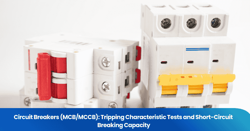
A circuit breaker that looks right, feels solid, and carries the correct markings but hasn't been properly tested is not a circuit breaker — it is a packaging box. When a fault occurs, the only thing standing between a short circuit and a fire is the reliability of that device's actual tested performance. For buyers sourcing MCBs and MCCBs from Chinese manufacturers, understanding how tripping characteristic tests and short-circuit breaking capacity tests are conducted — and what the numbers on a nameplate actually mean — is the difference between a compliant procurement and a liability.
This article explains the IEC standards that govern miniature circuit breakers (MCBs) and molded case circuit breakers (MCCBs), the specific tests that verify tripping curves and breaking capacity, and what a factory audit or pre-shipment inspection should check before you accept a shipment of circuit protection devices.
Key Takeaways
- MCBs are governed by IEC 60898-1 (residential/commercial use, up to 125A and 25kA); MCCBs for industrial distribution feeders are governed by IEC 60947-2 — using the wrong standard for your application is a safety and liability risk.
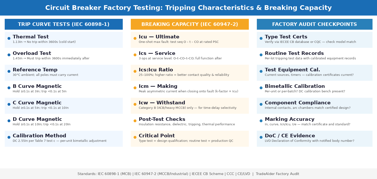
- Tripping characteristic tests verify two behaviors: thermal tripping (overload, tested at 1.13In and 1.45In) and magnetic (instantaneous) tripping (short-circuit, tested at multiples of In defined by the curve type — B, C, or D).
- Breaking capacity has two distinct ratings: Icu (ultimate — a one-shot test at maximum fault current) and Ics (service — three operations at the service current with the breaker remaining functional). Many low-cost breakers achieve their marked Icu but fail to maintain Ics reliability.
MCB vs. MCCB: The Standards That Govern Each
IEC 60898-1 for MCBs
IEC 60898-1 governs miniature circuit breakers for household and similar applications — the compact, DIN rail-mounted devices protecting final circuits in homes, offices, schools, and light commercial installations. The standard covers MCBs with a maximum rated current of 125A and a maximum breaking capacity of 25kA, classifying them by trip curves (B, C, and D) and specifying mandatory type tests covering temperature rise, tripping characteristics, dielectric strength, mechanical durability, and short-circuit breaking performance. Under IEC 60898-1, the breaking capacity rating is called Icn (rated short-circuit capacity), not Icu as it appears under IEC 60947-2 — a distinction that confuses buyers comparing breakers across the two standards.
IEC 60947-2 for MCCBs
IEC 60947-2 governs circuit breakers for industrial applications, covering low-voltage switchgear up to 1000V AC and 1500V DC. This is the standard for MCCBs used in distribution feeders, industrial panels, and anywhere the prospective short-circuit current (PSC) exceeds the range of IEC 60898 devices or where adjustable trip settings and higher breaking capacities are required. Under IEC 60947-2, breaking capacity is expressed as Icu (ultimate) and Ics (service), and the standard's test conditions are stricter than IEC 60898-1 — reflecting the higher energy fault levels in industrial environments.
A buyer sourcing MCBs for an industrial switchboard and accepting devices marked only to IEC 60898-1 may be installing breakers that were type-tested at less severe conditions than the installation environment demands. Using IEC 60898-style assumptions on a feeder that should be engineered under IEC 60947-2 is a common and dangerous mistake.
Tripping Characteristic Tests
Understanding trip curves: B, C, and D
Trip curves define the time-current relationship that governs when a breaker trips under overload and short-circuit conditions. All MCBs under IEC 60898-1 have two trip regions: a thermal region (slower, responding to sustained overloads via a bimetallic strip) and a magnetic region (instantaneous, responding to high short-circuit currents via a solenoid). The trip curve letter describes the magnetic trip threshold — specifically, the multiple of rated current (In) at which the magnetic (instantaneous) trip activates.
| Curve | No-Trip Hold (magnetic) | Instantaneous Trip Threshold | Typical Application |
|---|---|---|---|
| B | ≥ 0.1 s at 3In | Trips < 0.1 s at 5In | Cables, resistive loads, long cable runs |
| C | ≥ 0.1 s at 5In | Trips < 0.1 s at 10In | General distribution, standard loads |
| D | ≥ 0.1 s at 10In | Trips < 0.1 s at 20In | Motors, transformers, high inrush loads |
Curve C is used for standard distribution applications. Curve B is selected where short-circuit currents are relatively low (long cable runs, IT systems), and curve D is used where high inrush currents are expected, such as on motor-starting circuits. Selecting the wrong curve for an application causes either nuisance tripping (on inrush with a B curve) or delayed protection (with a D curve on a resistive load with low fault levels).
Thermal tripping tests: the 1.13In and 1.45In procedure
The thermal tripping test verifies that a breaker does not trip under moderate sustained overload (1.13 times rated current) but does trip within the specified time limit under 1.45 times rated current. The IEC 60898-1 test procedure requires that at 1.13In, the breaker does not trip within 3600 seconds (one hour), starting from cold. Immediately following this, the current is raised to 1.45In and the breaker must trip within a further 3600 seconds. The entire test is conducted at a reference ambient temperature of 30°C (±0 to +5°C).
In factory routine testing, this procedure is typically conducted at the production line on 100% of units for higher-specification products, or on a defined sampling basis for commodity MCBs. The bimetallic strip is the critical element — its mechanical calibration determines the tripping band. Factories with bimetallic calibration machines use a DC current test at 2.55In (as specified in IEC 60898-1 Table 7 test c) to calibrate each strip individually and adjust the trip mechanism to fall within a narrow specified tripping window.
Magnetic tripping tests: instantaneous verification
The magnetic (instantaneous) trip test verifies that the solenoid mechanism responds correctly to short-circuit currents. For IEC 60898-1 clause 9.10.2, the test involves two phases per curve type. First, a hold test confirms the breaker does not trip instantaneously at the no-trip threshold (3In for B, 5In for C, 10In for D) — the breaker must hold for at least 0.1 seconds at this level. Second, a trip test at the instantaneous trip threshold (5In for B, 10In for C, 20In for D) confirms the breaker trips in under 0.1 seconds.
This test requires specialised equipment capable of delivering precise high currents at short duration — a standard factory requirement for any MCB production line claiming IEC 60898-1 compliance. When auditing a factory, the absence of this equipment or inability to produce recent test records for the shipped production lot is a significant quality concern.
MCB/MCCB Factory Testing Overview — Tripping Characteristics and Short-Circuit Breaking Capacity
Short-Circuit Breaking Capacity: Icu, Ics, and the Difference That Matters
Ultimate breaking capacity (Icu) — a quality measure
Icu is the maximum short-circuit current that a circuit breaker can interrupt without catastrophic failure. Ultimate breaking capacity is a measure of quality of a circuit breaker — it represents the single worst-case scenario the device can survive. Critically, after an Icu-level fault interruption, the breaker has satisfied its safety obligation but is no longer required to remain operable. It may have experienced contact erosion, deformation, or partial internal damage — it simply must not fail catastrophically (arc explosion, fire, housing rupture) during the break operation.
The Icu test sequence under IEC 60947-2 is O-t-CO — one open operation (O), a wait of three minutes (t), then a close-open operation (CO). This two-operation sequence at the rated fault current constitutes the type test for ultimate breaking capacity. Under IEC 60898-1, the equivalent is Icn, tested similarly but under the standard's household-application test conditions.
Service breaking capacity (Ics) — a reliability measure
Ics is the maximum short-circuit current a circuit breaker can interrupt and continue to operate reliably afterward — not just survive once, but remain fully functional for continued service. The Ics test sequence is tougher than Icu: three back-to-back operations at the Ics level, followed by verification of insulation, tripping, and heat performance. A breaker that passes Ics testing has demonstrated that it can handle multiple fault events and continue to perform its protection function.
Ics is expressed as a percentage of Icu. Common values are 25%, 50%, 75%, and 100%. A breaker with Icu = 25kA and Ics = 50% Icu has a service breaking capacity of 12.5kA — meaning it can handle repeated faults up to 12.5kA and remain operational, but a single fault at 25kA may leave it unable to re-operate reliably. For critical applications — hospitals, data centres, process industries — Ics = 100% of Icu is the appropriate specification.
| Rating | Definition | Test Sequence (IEC 60947-2) | Post-Test Requirement |
|---|---|---|---|
| Icu | Ultimate breaking capacity — one-time maximum | O – t – CO | Basic isolation, dielectric strength |
| Ics | Service breaking capacity — repeatable | O – t – CO – t – CO (3-pole/4-pole) | Full function, insulation, tripping retained |
| Icm | Making capacity — peak asymmetric current | CO operation at specified phase angle | No welding of contacts, no damage |
| Icw | Short-time withstand (Category B only) | Withstand at rated current for defined time | No trip during defined delay period |
Icm (making capacity) and Icw (short-time withstand current) are two additional ratings that matter in specific applications. Icm becomes important in transfer switch applications or automatic reclosing systems where a breaker may close onto an existing fault. Icw applies only to Category B breakers (typically air circuit breakers and heavy-duty MCCBs) used in systems requiring time-delayed selectivity — where a downstream breaker must trip first while the upstream device withholds during the fault duration.
Type tests vs. routine production tests
A critical distinction that buyers must understand is the difference between type tests and routine production tests. Type tests — including the full Icu and Ics breaking capacity sequences — are conducted on representative samples during product design qualification and certification. They are expensive, destructive (the breakers used for breaking capacity tests are typically not resold), and require accredited laboratory facilities. Once a product design passes type testing, the manufacturer receives a certificate valid for that specific design.
Routine production tests are the quality checks conducted on production-line units — every unit, or a statistical sample. Routine tests do not repeat the full breaking capacity type test sequence. Instead, they verify electrical continuity, tripping characteristics (thermal and magnetic), dielectric strength, and mechanical operation within defined tolerances. The type test certificate establishes that the product design is capable; routine testing confirms that production units conform to the design.
When a buyer receives a circuit breaker "certificate" from a Chinese manufacturer, they should verify whether it is a type test certificate from an accredited laboratory (CB scheme, CCC, CE, UL) or a factory routine test record. The former provides meaningful safety assurance; the latter is a production quality record that is only meaningful if the factory's routine tests are comprehensive and documented.
TradeAider's factory audit for electrical protection devices specifically reviews type test certification status, routine test coverage and sampling plans, calibration records for test equipment, and whether the devices being produced match the certified design — checking for unauthorized component substitutions that maintain external appearance but alter internal performance.
What Factory Auditors Check for Circuit Breakers
Tripping characteristic verification
Auditors review the factory's production testing setup for thermal and magnetic tripping. Key findings include test benches that apply the correct 1.13In and 1.45In currents with servo-controlled accuracy, timer resolution adequate to measure magnetic trip times under 100 milliseconds, documented calibration records for current sources and timers (test equipment used at the wrong current level produces invalid results), and traceability from production lot to test data records.
A factory that tests tripping characteristics only at the start of a production run, or tests a single sample per shift rather than per production lot, is operating with a quality system that may not catch bimetallic strip calibration drift across a production run. The consequence is a shipped lot with a distribution of trip times wider than the IEC specification allows.
Breaking capacity documentation
For breaking capacity, auditors check the type test certificates against the actual products being shipped. This involves verifying that the model numbers, ratings, and construction details on the certificate match the production units, checking that certificates are from accredited laboratories (CB scheme, CCC for China market, CE marking with appropriate notified body) and within their validity period, and reviewing whether the manufacturer has any undisclosed design changes since the original type test — a practice that invalidates the certificate but is not always disclosed.
A specific and frequently encountered issue in Chinese MCB manufacturing is the use of type test certificates for one product family applied to a nominally similar but actually different product. Nameplate markings may be identical, but the internal contact geometry, arc chamber design, or bimetallic material specification may differ from the certified design. An auditor who reviews both the certificate's technical detail and the production device's internal construction can identify this discrepancy.
Marking and labeling verification
Both IEC 60898-1 and IEC 60947-2 require specific markings on circuit breakers: rated current (In), trip curve letter (B, C, D for MCBs), breaking capacity (Icn or Icu/Ics), rated voltage (Ue), and the applicable standard. A pre-shipment inspection of circuit breakers always includes marking verification — confirming that labels are legible, durable, accurate, and consistent with the supporting documentation. Discrepancies between a nameplate marking and the type test certificate (e.g., a higher Icn marked than the certificate covers) are grounds for immediate rejection.
For buyers importing circuit breakers for EU or UK markets, CE marking under the Low Voltage Directive (2014/35/EU) requires that the device conforms to harmonised standards including IEC/EN 60898-1 or IEC/EN 60947-2. CE markings on Chinese MCBs without a DoC (Declaration of Conformity) referencing the harmonised standard and an identified responsible party are non-compliant and expose importers to market surveillance action.
Common Quality Failures in Chinese MCB/MCCB Production
Bimetallic strip calibration drift
The bimetallic strip is the most mechanically sensitive component in an MCB. Its curvature under heat — and therefore its trip time under overload — depends on the properties of the bonded metal layers, their thickness ratio, and the mechanical adjustment of the trip lever. Factories that calibrate strips only at the beginning of a production run, or that rely on batch acceptance testing rather than per-unit calibration, regularly ship lots where the tripping time distribution spans both sides of the IEC 60898-1 tolerance. Buyers who independently test incoming MCBs at 1.45In frequently find units that trip in under 60 seconds (too sensitive, causing nuisance tripping) alongside units that require more than 2,000 seconds (dangerously slow).
Contact material and breaking capacity reliability
The arc-extinguishing contacts and arc chamber geometry determine whether a breaker can achieve and sustain its rated breaking capacity. Contact erosion during a high-current interruption event is the primary mechanism limiting Ics performance. Factories using lower-quality contact materials or simplified arc chamber designs can produce breakers that pass Icu type testing (a single event at a certified laboratory) but show degraded tripping reliability after field fault events — manifesting as contacts that weld, breakers that fail to trip on subsequent faults, or cases that deform under arc energy.
For buyers procuring circuit breakers for critical distribution applications, the Ics-to-Icu ratio on the product label is the key indicator of contact quality investment. A ratio of 100% (Ics = Icu) indicates the manufacturer has validated service performance after multiple fault events. A ratio of 25% suggests the breaker is rated for single-fault protection only — adequate for some applications, insufficient for others.
To verify circuit breaker quality before committing to a supplier, TradeAider's inspection team can review production test records during a factory audit, perform AQL-based incoming sampling with tripping characteristic verification, and confirm type test certificate authenticity. For buyers with specific electrical safety compliance requirements, TradeAider's product testing services can coordinate laboratory type test verification where required. Contact us via the enquiry page to discuss the scope.
Frequently Asked Questions
What is the difference between Icn (IEC 60898) and Icu (IEC 60947-2)?
Both represent the maximum short-circuit current the breaker can interrupt without catastrophic failure, but they are tested under different conditions reflecting the standards' different application scopes. Icn under IEC 60898-1 is the breaking capacity for household circuit breakers, tested to conditions appropriate for residential and light commercial systems. Icu under IEC 60947-2 applies to industrial switchgear with more severe test parameters. An MCB marked with Icn = 6kA to IEC 60898-1 is not directly comparable to an MCCB with Icu = 6kA to IEC 60947-2 — the IEC 60947-2 device has been verified to more demanding test conditions. Buyers should not mix standards when selecting devices for a single installation.
How can I tell if a Chinese MCB's type test certificate is genuine?
Genuine type test certificates under the CB scheme (IECEE) are traceable through the IECEE's public certificate database at iecee.org. CE declarations of conformity should name a notified body with a valid EU registration number for LVD (Low Voltage Directive) scope. CCC certificates for China-market products are verifiable through China's CQC certification body. Red flags include certificates with no laboratory accreditation number, certificates issued by unknown or unverifiable bodies, certificates that do not specify the exact model, ratings, and test standard covered, and certificates where the named product model does not match the markings on the physical device. An independent factory audit can compare the certificate documentation against the actual production devices to identify discrepancies.
Why does an MCB marked 10kA sometimes fail to break a 6kA fault reliably?
The Icu marking indicates the maximum fault current the breaker can interrupt without catastrophic failure — a type-test result on a laboratory sample. It does not guarantee repeated reliable interruption at lower currents, which is what Ics measures. If a breaker is marked 10kA Icu with Ics = 25% (2.5kA), it is only verified for repeated service interruption up to 2.5kA. A 6kA fault may be within the Icu range and survivable once, but if the contact geometry and arc chamber design are optimised only for the minimum Ics, repeated lower-level faults will progressively degrade the breaker. This is why Ics-to-Icu ratio, not just Icu rating, is the meaningful specification for service environments.
What happens after an MCB trips on a genuine short circuit — can it be reset and used again?
Whether a breaker can be safely reset after a fault trip depends on the magnitude of the fault current it interrupted relative to its Ics rating. If the fault current was within the breaker's Ics value, the breaker can be reset and returned to service after the fault cause has been rectified. If the fault current was above Ics but within Icu, the breaker interrupted the fault safely but its continued reliable operation is not guaranteed — inspection for contact erosion, arc scoring, housing deformation, and thermal damage is necessary before resetting. A breaker that has interrupted a fault at or near its Icu limit should be treated as suspect and replaced unless a qualified inspection confirms its integrity. Any breaker that shows cracked housing, a burnt smell, visible arc damage, or difficulty in mechanical operation after a fault must be replaced regardless of its rated capacity.
Related Articles

Grow your business with TradeAider Service
Click the button below to directly enter the TradeAider Service System. The simple steps from booking and payment to receiving reports are easy to operate.