- Acerca de Nosotros

- Nuestros Servicios
- Su Industria
- Recursos
- Noticias y Blog
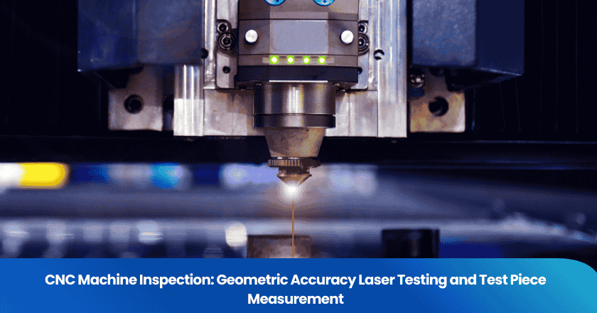
Buying a CNC machining center from a Chinese manufacturer without a rigorous geometric accuracy inspection is one of the most expensive mistakes a machine shop can make. The machine may look impressive on the showroom floor and run smoothly during a brief demonstration — but if the linear axes are not straight, the spindle runs out, or the rotary axes are not perpendicular to each other, every part it ever produces will be wrong. Not obviously wrong in the first week, but consistently, systematically wrong — in ways that accumulate through your production tolerances and eventually surface as scrap, rework, and lost customers.
This guide explains the two primary methods for verifying CNC machine geometric accuracy before acceptance — laser interferometry-based volumetric testing and standardized test piece cutting — and how each method is used, what it reveals, and when to use them together.
Key Takeaways
- Laser interferometry measures individual axis errors (positioning, straightness, squareness) with sub-micron resolution — it is the definitive method for geometric accuracy verification under ISO 230-2.
- Test piece cutting measures the integrated performance of the machine under actual cutting conditions — it reveals errors that only appear when all axes and the spindle work together under load.
- A complete CNC acceptance inspection requires both methods: laser testing alone misses thermal and dynamic errors; test piece alone cannot isolate which axis is causing a given deviation.
Why CNC Geometric Accuracy Matters More Than the Specification Sheet
The Gap Between Specified and Achieved Accuracy
CNC machine manufacturers publish geometric accuracy specifications in their sales materials — positioning accuracy of ±0.005 mm, repeatability of ±0.002 mm, spindle runout of less than 0.003 mm. These numbers come from the ISO 230 standard series, which defines exactly how each parameter should be measured. The problem is that a specification number on a data sheet does not guarantee the specific machine sitting on the factory floor meets that number. It describes what the machine type is designed to achieve, not what this particular machine has been verified to achieve.
Geometric accuracy inspection, conducted before acceptance and payment, answers the question that the specification sheet cannot: does this specific machine, with its specific assembly tolerances, thermal state, and geometric calibration, actually meet the accuracy requirements of your applications?
According to the ISO 230-1 standard — which defines the geometric accuracy test methods for machine tools — a complete acceptance test covers six geometric error types per linear axis: positioning error, reversal error, straightness in two planes, and angular error in three axes (pitch, yaw, roll). For a three-axis machining center, this means up to 18 individual error measurements before the volumetric accuracy is characterized. (ISO 230-1: Test Conditions for Metal Cutting Machine Tools)
Consequences of Accepting a Geometrically Inaccurate Machine
The cost of geometric errors in CNC machines is not linear — it compounds through every part the machine produces. A 0.01 mm squareness error between the X and Y axes produces a 0.01 mm diagonal error in every rectangular pocket the machine cuts. For a machine shop producing 1,000 parts per month, this error is present in every single part. Depending on the part tolerance, this means consistent scrap, systematic rework, or — worst case — parts that pass your CMM but fail at your customer's assembly, where tolerances stack with other components.
Correcting geometric accuracy errors after a machine is installed and in production is possible but disruptive. Many geometric errors require the machine to be taken out of service, moved, and recommissioned. Some errors — like a worn or incorrectly ground spindle bearing — require factory-level repair. Identifying and rejecting these errors before the machine leaves the supplier's facility is dramatically more efficient.
Method 1: Laser Interferometry Testing
How Laser Interferometry Works
A laser interferometer measures linear displacement by counting interference fringes in a laser beam that is split, reflected off a moving retroreflector (mounted on the machine axis), and recombined with the reference beam. The resulting interference pattern changes by one fringe for every half-wavelength of laser light (approximately 316 nm for a helium-neon laser) of axis movement. This gives the instrument sub-micron resolution over measurement ranges of several meters — far beyond the capability of dial indicators or electronic probes for axis-level geometric testing.
The most widely used instruments for machine tool geometric testing are the Renishaw XL-80 and XC-80 systems, and the Optodyne MCV series, both of which automate measurement acquisition through software interfaces to the machine's CNC controller. (Renishaw XL-80 Laser System)
The Six Axis-Level Tests in ISO 230-2
ISO 230-2 defines the standard methodology for measuring positioning accuracy and repeatability of CNC axes. A full test commands the axis through a defined series of positions across its full travel range, measures the actual position achieved at each target, and calculates the statistical metrics defined in the standard. The key measurements are mean bidirectional positioning deviation (A), mean reversal value (B), and systematic positioning deviation (E), along with the repeatability metrics R↑ and R↓ for each direction of travel.
Beyond ISO 230-2 positioning tests, a complete geometric accuracy assessment covers straightness (how much the axis deviates laterally as it moves), angular errors (pitch, yaw, and roll about each axis), and squareness between axis pairs. The squareness error between X-Y, X-Z, and Y-Z planes is particularly critical because it determines the geometric accuracy of all prismatic features the machine can produce.
Ball Bar Testing: Fast Machine Health Check
A ball bar test (standardized under ISO 230-4) is a faster, lower-cost alternative to full laser testing for assessing circular interpolation accuracy — how accurately the machine traces a circular path in two simultaneous axes. A telescoping bar with precision ball ends connects a fixed mount (on the machine table) to a mount on the spindle. As the machine executes a circular program, the ball bar measures the actual radius versus the commanded radius as a function of angular position.
The polar plot output of a ball bar test visually reveals a diagnostic signature for specific machine errors: squareness error produces an elliptical plot; backlash shows as flat spots at axis reversals; servo mismatch produces a four-lobed clover pattern; stick-slip (stiction) produces irregular spikes at low feed rates. Ball bar testing is an excellent screening tool — it identifies machines with significant geometric or servo problems quickly — but it does not provide the individual axis-level error data needed to specify corrective action. (Renishaw Ball Bar Testing)
Laser Measurement Summary: Errors, Methods, and Standards
| Error Type | Measurement Method | ISO Standard | Typical Acceptance Limit (3-axis VMC) |
|---|---|---|---|
| Linear Positioning | Laser interferometer + retroreflector | ISO 230-2 | ±0.005 mm / 300 mm travel |
| Straightness (H & V) | Laser with straightness optics | ISO 230-1 | 0.010 mm over full travel |
| Angular (Pitch/Yaw/Roll) | Laser with angular optics | ISO 230-1 | 10 arcseconds over full travel |
| Squareness (XY, XZ, YZ) | Laser with squareness optic / granite square | ISO 230-1 | 0.010 mm / 300 mm |
| Circular Interpolation | Ball bar (telescoping) | ISO 230-4 | ±0.005 mm roundness |
| Spindle Runout (radial) | Precision test mandrel + electronic probe | ISO 230-7 | <0.003 mm at 50 mm from nose |
Method 2: Test Piece Cutting
What a Test Piece Measures That Laser Testing Cannot
Laser testing measures static geometric errors — the geometry of the machine axes when moving slowly and without cutting load. It does not measure dynamic errors that appear during actual cutting: the combined effect of servo gain mismatch, thermal growth during cutting, vibration from spindle and cutting forces, and the real performance of the CNC interpolation algorithms under commanded feed rates.
Test piece cutting fills this gap. A standardized test piece, cut in a specified material (typically aluminum alloy 6061-T6 or steel) at defined feeds, speeds, depths, and tool paths, produces a physical artifact that can be measured on a CMM. The deviations measured on the test piece are the integrated result of all error sources — geometric, dynamic, thermal, and control — that affect part accuracy in real production conditions.
The most widely referenced standard for CNC machining center test pieces is the NAS 979 (National Aerospace Standard) circular and linear test piece, which combines a circular pocket (testing circular interpolation), a 45° linear slot (testing combined-axis interpolation), a square pocket (testing perpendicularity), and a series of holes (testing positioning and Z-axis accuracy) in a single part. (NAS 979 Machining Center Test Piece Standard)
How to Specify a Test Piece for CNC Acceptance
The test piece specification should be written into the purchase agreement, not left to the supplier to define at acceptance time. Key parameters to specify include the material and material specification (supplier-provided material introduces a variable that makes results harder to interpret), the cutting tools and tool holders (carbide inserts, grade, and insert geometry affect surface finish and dimension achievability), the feeds and speeds (too conservative a feed rate hides servo and vibration issues that appear at production parameters), and the measurement method and acceptance criteria for each feature.
The measurement criteria should reference specific tolerances that are tighter than your typical production requirements — the test piece is intended to challenge the machine, not to demonstrate it can hold tolerances two orders of magnitude larger than the positioning accuracy specification.
Thermal Warm-Up and Environmental Conditions
The environment in which geometric accuracy tests are conducted significantly affects results. ISO 230-1 specifies that accuracy measurements should be conducted at 20°C ±2°C with temperature change not exceeding 1°C per hour. Chinese factory floors are rarely temperature-controlled to this standard, and the machine's thermal state at the time of measurement — whether it has been running for two hours or has been sitting overnight — substantially affects the geometric results due to thermal growth in the spindle, headstock, and ball screws.
Before any geometric acceptance test, the machine should be thermally stabilized through a defined warm-up cycle (typically 30 to 60 minutes of programmed axis motion and spindle running at production RPM). Any acceptance test conducted immediately after startup on a cold machine in an uncontrolled environment is not representative of the machine's steady-state performance — and suppliers who present geometric test results under these conditions are not showing you the worst case.
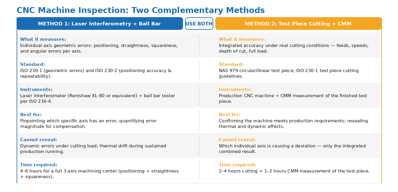
Figure 1. CNC geometric accuracy inspection: laser testing measures individual axis errors; test piece cutting measures integrated accuracy under real cutting conditions.
Spindle Accuracy Testing: The Critical Variable Most Buyers Miss
Spindle Runout and Its Effect on Machined Accuracy
Spindle accuracy is the element of CNC machine geometric performance most directly connected to the accuracy of machined holes, bores, and cylindrical features. Spindle radial runout — the displacement of the spindle centerline as it rotates — directly adds to the error budget of any bored or reamed hole. A spindle with 0.005 mm radial runout will produce bored holes that are at minimum 0.005 mm oversize and potentially non-round by the same amount.
ISO 230-7 defines three spindle accuracy parameters: radial motion (runout), axial motion (end-thrust wobble), and tilt motion (the change in spindle axis direction as it rotates). All three should be measured with a precision test mandrel and an electronic probe with a resolution of at least 0.001 mm, at multiple distances from the spindle nose (typically 50 mm and 150 mm from the nose) and at multiple RPMs including the spindle speed most relevant to your production applications.
Thermal Growth of the Spindle
Spindle thermal growth — the elongation of the spindle axis as the spindle bearings heat up during operation — is one of the most significant sources of Z-axis error in CNC machining. On an uncompensated machine, spindle thermal growth of 0.02 to 0.05 mm over the first 30 minutes of operation is common. This means that a hole depth programmed as 25.000 mm will be cut as 25.020 to 25.050 mm after the spindle has warmed up — an error that appears gradually as the spindle heats and then stabilizes.
Modern machining centers use thermal compensation algorithms that measure spindle temperature through embedded sensors and correct the Z-axis commanded position. A spindle thermal growth test — measuring Z-axis position drift over a 60-minute spindle warm-up at production RPM — verifies that this compensation is working correctly. This test is rarely included in supplier-prepared FAT protocols and must be explicitly specified by the buyer.
Practical Protocol for CNC Machine Acceptance Inspection
Sequence the Tests Correctly
The sequence in which CNC acceptance tests are conducted matters. Conducting test piece cutting before geometric laser testing gives the machine time to thermally stabilize during the cuts — but if the test piece reveals geometric errors, you then need the laser testing to identify which axis is responsible. A practical acceptance inspection sequence is: (1) geometric laser testing in the morning after a 60-minute warm-up; (2) ball bar test immediately after laser testing; (3) spindle accuracy tests; (4) test piece cutting at production feeds and speeds; and (5) CMM measurement of the test piece. The entire sequence for a three-axis machining center typically requires one full working day.
Who Should Conduct the Testing
Geometric accuracy testing requires specialized equipment and trained metrology personnel. The supplier's own metrology team can conduct the tests under third-party witness — this is the typical FAT model, where the supplier performs the tests and the inspector witnesses and records the results. Alternatively, a third-party inspection service can provide or arrange the measurement equipment and certified metrology technicians to conduct independent testing.
For buyers sourcing CNC equipment from China, the challenge is finding inspection personnel with both the metrology expertise to operate laser interferometers and ball bars correctly and the China-based presence to be on the factory floor when needed. TradeAider's pre-shipment inspection services and factory audit service can be coordinated with your technical acceptance requirements — providing independent on-site presence and real-time reporting so you see test results as they are recorded, not in a summary two days after the test.
Handling Out-of-Specification Findings
When laser testing reveals an axis that does not meet specification, the supplier has several potential corrective actions depending on the error type and magnitude. Positioning errors and ball screw backlash can often be corrected through CNC controller parameter adjustment (pitch error compensation, backlash compensation) — these are software corrections that improve the as-programmed accuracy but do not correct the underlying mechanical error. Straightness and squareness errors in the machine structure require physical adjustment — realignment of guideways, shimming of axis saddles — which is a more significant intervention that may require 24 to 48 hours of machine downtime.
The acceptance criteria in the purchase agreement should distinguish between errors that can be corrected through controller compensation (acceptable with documentation of the compensation values) and errors that require mechanical correction (requiring re-test after repair). Accepting a machine with positioning errors that have been purely software-compensated, without documenting the compensation table values, means you do not know the actual mechanical state of the machine and cannot detect if the error grows over time.
Frequently Asked Questions
What is the difference between positioning accuracy and repeatability in CNC machines?
Positioning accuracy describes how closely the machine arrives at a commanded position — measured as the deviation between the commanded and actual position, averaged across multiple approaches. Repeatability describes how consistently the machine returns to the same position across multiple moves — a machine can have poor absolute accuracy (systematic offset from commanded position) but excellent repeatability (very consistent offset), which can be compensated in the CNC controller. For production applications where part programs are written with tool length compensation and workpiece offsets, repeatability is often more important than absolute positioning accuracy for day-to-day part quality.
Do I need a third-party inspection if the machine supplier provides geometric test certificates?
Supplier-provided test certificates document the test results the supplier chose to record and report — they do not verify that the tests were conducted correctly, that the machine was in representative thermal condition during testing, or that the acceptance criteria used match your purchase specification. An independent third-party witness — or independent testing — provides verification that the tests were conducted per the agreed protocol and that the results are representative of the machine's actual performance. For equipment being shipped internationally, third-party verification certificates also provide documentation that supports insurance claims and dispute resolution if problems emerge after delivery.
How do I specify CNC machine accuracy requirements in the purchase order?
Reference specific ISO 230 series parameters by name and number (e.g., "positioning accuracy E per ISO 230-2 ≤ 0.008 mm over 500 mm travel"), specify the test conditions (thermal warm-up duration, ambient temperature range, test equipment minimum specification), and include the NAS 979 test piece or equivalent with specific dimensional acceptance criteria. Generic accuracy specifications like "±0.005 mm positioning accuracy" without a referenced standard are difficult to verify and even more difficult to enforce if disputed.
Can CNC geometric accuracy degrade over time?
Yes. CNC machine geometric accuracy degrades through normal use due to guideway wear, ball screw wear, spindle bearing wear, and thermal cycling. A machine that passes acceptance testing accurately may drift out of specification over months or years of production, particularly if the machine is used at high duty cycle, cutting abrasive materials, or operated without proper lubrication and maintenance. Establishing a documented baseline of geometric accuracy at acceptance gives you the reference point needed to identify when re-calibration or mechanical maintenance is required — which is another reason why a thorough acceptance inspection is valuable beyond the immediate acceptance decision.
Conclusion
Accepting a CNC machining center without a structured geometric accuracy inspection — laser testing, ball bar assessment, and test piece cutting — means accepting unknown risk into every part your shop will ever produce on that machine. The investment in proper acceptance testing, whether conducted by your own metrology team or by an independent third-party inspector with witnessed testing at the supplier's facility, is a fraction of the cost of discovering a geometrically inaccurate machine after it is installed and in production.
For buyers sourcing CNC equipment and other capital machinery from Chinese manufacturers, TradeAider offers inspection and audit services with real-time reporting — so your technical team can see measurements and findings as they happen and direct the on-site inspector in real time. Contact TradeAider to discuss your equipment acceptance inspection requirements, or use the Inspection Charge Calculator to estimate costs.
Artículos Relacionados


Haga crecer su negocio con el Servicio TradeAider
Haga clic en el botón de abajo para ingresar directamente al Sistema de Servicios TradeAider. Los pasos simples desde la reserva y el pago hasta recibir los informes son fáciles de operar.