- Acerca de Nosotros

- Nuestros Servicios
- Su Industria
- Recursos
- Noticias y Blog
A flow meter that reads incorrectly does not fail dramatically — it fails silently. A custody transfer meter that reads 2% high overbills your customer on every unit sold. A process flow controller that reads 5% low runs your reaction at the wrong stoichiometry for months before the cause is identified. A gas consumption meter that drifts with temperature reports your energy usage inaccurately for the duration of its service life. In each case, the error was present from the day the meter was installed, could have been identified with a proper incoming calibration, and was not.
This guide covers the two critical incoming inspection tests for flow meters: flow calibration (including the different approaches for liquid versus gas applications) and output signal stability testing. Together, these tests verify that a flow meter will report the correct flow rate accurately and consistently before it is installed.
Key Takeaways
- Flow calibration verifies accuracy across the meter's operating range — from minimum flow (low-flow cutoff) to maximum rated flow — and must use a reference standard with known uncertainty appropriate to the meter's accuracy class.
- Liquid and gas calibration require fundamentally different reference standards and correction methods: liquid calibration uses gravimetric or volumetric master meters; gas calibration requires additional corrections for temperature, pressure, and compressibility.
- Output signal stability testing — verifying that the 4-20 mA, pulse, or digital output is stable, accurate, and correctly scaled — is separate from flow calibration and is frequently omitted from factory calibration procedures.
Flow Meter Types and Their Calibration Approach
Why Calibration Method Depends on Meter Technology
Flow meter technology determines both the physical principle being calibrated and the potential failure modes that calibration must detect. The most common flow meter technologies in industrial use each respond differently to calibration errors and environmental conditions.
Differential pressure (DP) flow meters (orifice plates, Venturis, flow nozzles) measure flow by the pressure drop across a primary element — calibration verifies the pressure differential measurement and the primary element's flow coefficient (C_d). Electromagnetic flow meters (magmeters) measure velocity of conductive liquids by the EMF induced in an applied magnetic field — calibration is a volumetric comparison against a reference standard, and the meter has no moving parts to wear. Ultrasonic flow meters measure transit-time of acoustic signals — calibration verifies the velocity calculation and compensates for pipe geometry. Coriolis flow meters directly measure mass flow through the inertia of oscillating tubes — calibration is mass-based rather than volumetric. Turbine flow meters and positive displacement meters have mechanical sensing elements whose wear directly affects calibration over time.
OIML (International Organisation of Legal Metrology) R 117-1 defines the accuracy classes and test requirements for liquid flow meters used in custody transfer, which is the most stringent calibration standard applicable to commercial flow measurement. (OIML R 117-1 — Dynamic Measuring Systems for Liquids)
Liquid Flow Calibration
Reference Standards for Liquid Calibration
Liquid flow calibration compares the meter's output against a reference standard that measures the same flow with known uncertainty. The two dominant reference standard types for liquid calibration are gravimetric systems and master meter comparisons.
A gravimetric calibration system directs the flow through the meter under test and simultaneously into a weigh tank. The mass of liquid collected over a precisely measured time interval, divided by time, gives the reference mass flow rate with uncertainty typically in the range of ±0.05% to ±0.1%. This is the primary standard method for high-accuracy liquid calibration and is used for Coriolis, turbine, and electromagnetic meters in custody transfer applications.
Master meter calibration uses a reference flow meter with a current calibration traceable to a national measurement standard, installed in series with the meter under test. The ratio of the test meter's output to the master meter's output at each flow rate gives the test meter's error. This method is faster and more practical for production lot calibration but inherits the master meter's uncertainty — for a master meter with ±0.1% uncertainty, the achievable calibration uncertainty is typically ±0.2% to ±0.3% when including all systematic sources.
The Calibration Curve: Linearity and Repeatability
Flow meter calibration is not a single-point check. A calibration curve — the meter's error plotted as a function of flow rate from minimum to maximum — is the fundamental accuracy characterization for a flow meter. Most flow meters show systematic variation in error across their flow range: magnetic flow meters are typically very linear; turbine meters show a characteristic curve with higher errors at low flow rates near the minimum flow; Coriolis meters are extremely linear across a very wide range.
A proper flow calibration tests the meter at a minimum of 5 flow rates distributed across the range from 10-20% of maximum flow (Q_min verification) up to 100% of maximum flow (Q_max). The linearity of the calibration curve — the consistency of the meter factor (K-factor or calibration coefficient) across the flow range — determines whether the meter can be adequately represented by a single calibration factor or requires a multi-point correction table loaded into the transmitter.
Repeatability at each flow point — the consistency of the meter's output across multiple readings at steady flow — is tested by taking at least three consecutive readings at each flow rate and calculating the spread. ISO 4185 (the standard for measurement of liquid flow in closed conduits by weighing method) specifies test procedures that include repeatability assessment as an integral part of the calibration protocol. (ISO 4185 — Measurement of Liquid Flow in Closed Conduits by Weighing Method)
Minimum Flow Verification: The Most Commonly Skipped Test
The minimum flow verification — testing the meter's accuracy at or near its specified minimum measurable flow rate — is the test that most supplier calibration certificates omit or under-test. At low flow rates, turbine meters are affected by bearing friction and starting torque; electromagnetic meters are affected by noise-to-signal ratio; differential pressure meters face their lowest differential pressure signal and are most affected by zero drift in the DP transmitter.
A meter that is calibrated only at 50% and 100% of range may read accurately at those points but fail significantly near minimum flow — an error that will appear in any application that involves startup ramping, batch dosing to target weight, or process turndown to low production rates. Specifying minimum flow calibration in the purchase order and the calibration certificate is the practical solution.
Gas Flow Calibration
Additional Complexity: Temperature, Pressure, and Compressibility
Gas flow calibration introduces complexities that are absent in liquid calibration. Unlike liquids, gas density varies significantly with temperature and pressure — a volumetric flow measurement of gas is only meaningful when the temperature and pressure at the measurement point are specified and recorded. Gas flow measurements are typically reported in one of two ways: actual volumetric flow (at the actual temperature and pressure at the meter), or normalized volumetric flow (corrected to standard reference conditions, typically 0°C or 15°C and 101.325 kPa). The distinction matters significantly for billing and process control.
For real gases, particularly those deviating from ideal gas behavior at high pressures — natural gas, carbon dioxide, hydrocarbon vapors — compressibility correction (the Z-factor) must be applied to the flow calculation. Errors in the Z-factor calculation introduce systematic flow errors that are proportional to the deviation of the gas from ideal behavior. AGA Report No. 8 (the industry standard for natural gas compressibility) specifies the calculation methods required for natural gas measurement. (AGA Report No. 8 — Compressibility Factors of Natural Gas)
Gas Calibration Reference Standards
The primary reference standards for gas flow calibration are bell provers (for low-pressure, low-flow applications such as gas meters for residential use), piston provers (for medium-flow applications), and sonic nozzles (critical flow venturis, used as transfer standards for high-flow calibration). For most industrial gas flow meters being inspected at factory acceptance, calibration is performed on a calibration rig using a reference master meter or sonic nozzle array that has been calibrated against national standards.
For thermal mass flow meters — widely used for gas flow measurement in process industries — the calibration medium matters significantly. Most manufacturers calibrate thermal mass flow meters using nitrogen or air; if the meter will be used with a different gas, a gas composition correction factor (K-factor for the actual gas versus the calibration gas) must be applied. Accepting a thermal mass flow meter calibrated in air for use with natural gas, without verifying that the correct gas K-factor has been programmed into the transmitter, is a common source of systematic flow measurement error.
Output Signal Stability Testing
Why Signal Testing Is a Separate Inspection Step
Flow meter calibration verifies that the sensing element correctly measures flow. Output signal testing verifies that the transmitter electronics correctly convert that measurement into the output signal — 4-20 mA analog current, pulse train, HART digital, Profibus, or Modbus — that the plant's DCS, PLC, or SCADA system will receive. These are two separate potential failure sources, and flow calibration alone does not verify signal output accuracy or stability.
The distinction matters in practice. A flow meter can have a perfectly calibrated flow element and a transmitter with a drifting 4-20 mA output — the flow measurement is correct internally but the signal reaching the control system is wrong. A pulse output meter can have correct calibration but incorrect K-factor programming — the control system receives accurate pulse counts but converts them to incorrect flow units because the K-factor loaded into the flow computer does not match the meter's calibration. Signal testing catches both these failure modes.
4-20 mA Output Accuracy and Linearity
For meters with 4-20 mA analog outputs, signal testing verifies three parameters: zero accuracy (the output current at zero flow should be 4.00 mA ± the specified tolerance), span accuracy (the output current at full-scale flow should be 20.00 mA ± the specified tolerance), and linearity (the output at intermediate flow rates should be linear with flow rate, with errors within the transmitter's specified output accuracy).
Signal testing is performed using a calibrated milliammeter and a reference voltage source for zero and span verification. For linearity testing, the meter is operated at controlled flow rates while the milliammeter output is recorded and compared against the expected value based on the calibration curve. A common finding is transmitter output that is accurately scaled at 4 mA and 20 mA but shows non-linearity at intermediate values — an error that would not be detected by zero and span checks alone.
Pulse Output Stability and Noise
Turbine meters, oval gear meters, and other pulse-output flow meters generate a train of pulses where each pulse represents a fixed volume of flow (the meter's K-factor, in pulses per unit volume). Signal stability testing for pulse output meters verifies K-factor consistency (the measured pulse output at a known flow rate gives the correct K-factor within tolerance), pulse frequency at minimum and maximum flow (minimum flow generates a minimum pulse frequency above the flow computer's minimum frequency threshold; maximum flow does not exceed the maximum frequency), and pulse noise immunity (the meter does not generate spurious pulses at zero flow or low flow).
Spurious pulsing at zero flow — false pulses generated by the meter's electronics when there is no actual flow — is a fault mode that affects batch totalization and consumption monitoring systems. A meter with 0.5 pulses per second of zero-flow noise adds approximately 1,800 phantom "pulse units" per hour to the totalized flow reading, regardless of the actual flow. This error only appears in systems that totalize flow over time, not in systems that only monitor instantaneous flow rate.
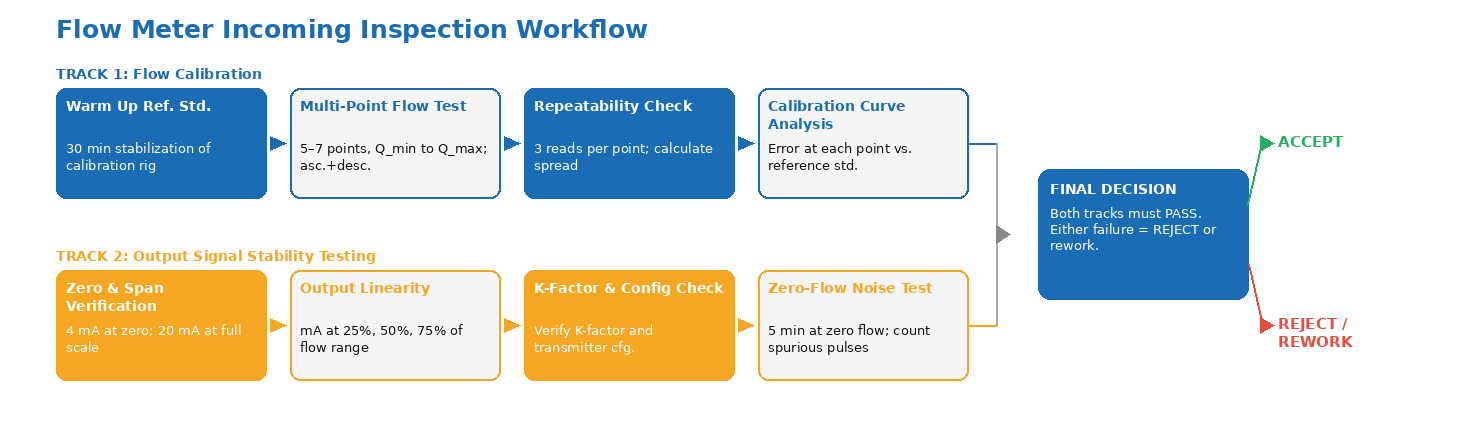
Figure 1. Flow meter incoming inspection workflow: flow calibration and output signal stability testing address different failure modes and must both be completed for a valid acceptance result.
Flow Meter Inspection Parameter Summary
| Test | What It Verifies | Liquid / Gas | Key Standard | Acceptance Criterion |
|---|---|---|---|---|
| Flow Calibration (multi-point) | Accuracy and linearity vs. reference standard across Q_min to Q_max | Both | OIML R 117 / ISO 4185 | Error ≤ MPE at all test points |
| Repeatability at Each Flow Point | Consistency of 3+ readings at same flow rate | Both | ISO 4185 / OIML R 117 | Spread ≤ 0.5× MPE |
| Minimum Flow Verification | Accuracy at Q_min; starting behavior | Both | Meter specification + application req. | Stable reading; error within class MPE |
| 4-20 mA Output Zero & Span | Output at 0% and 100% flow | Both | IEC 60770 / transmitter spec | 4.00 mA ±0.02 mA; 20.00 mA ±0.02 mA |
| Output Linearity | Output accuracy at intermediate flow rates | Both | IEC 60770 | Error ≤ transmitter accuracy spec |
| Pulse Output K-Factor Verification | Pulse/unit volume at calibration flow | Both (pulse output meters) | Meter calibration certificate | K-factor matches certificate ±tolerance |
| Zero-Flow Noise (Spurious Pulsing) | Pulse output at confirmed zero flow | Both (pulse output) | Meter specification | Zero pulses over 5-minute observation |
Calibration Certificate Verification: What to Check Before Accepting
The Difference Between a Calibration Certificate and a Test Report
Chinese flow meter manufacturers routinely ship meters with documentation labeled "Calibration Certificate" that does not meet the minimum requirements for a valid calibration certificate. A valid calibration certificate must identify the meter by serial number and model, state the calibration fluid (liquid or gas type, including composition for gas), record the temperature and pressure at the calibration point, identify the reference standard used and its traceability, record the measured flow rate and reference flow rate at each test point, calculate the error and K-factor at each point, state the expanded uncertainty of the calibration, and be signed by the responsible metrologist or laboratory.
A document that records only "tested at 50%, 100% of range — PASS" without the underlying measurement data is a test report, not a calibration certificate, and does not provide the information needed to verify that the meter meets your accuracy requirement.
NIST Traceability and ISO 17025 Accreditation
For flow meters used in custody transfer, safety-critical measurement, or applications where measurement uncertainty must be formally characterized, the calibration laboratory should hold ISO/IEC 17025 accreditation for the specific calibration scope (liquid flow, gas flow, applicable meter types). ISO 17025 accreditation verifies that the laboratory has demonstrated competence to perform calibrations to specific measurement standards with documented and validated uncertainty budgets. (ISO/IEC 17025 — Competence of Testing and Calibration Laboratories)
For meters sourced from Chinese manufacturers, the calibration laboratory used by the supplier should be verified as either ISO 17025-accredited or as using reference standards with documented traceability to the National Institute of Metrology (NIM) of China or another national metrology institute. Unverifiable or self-declared calibration traceability is a significant quality risk for any precision measurement application.
Common Findings in Flow Meter Inspection from Chinese Manufacturers
Calibration Fluid Mismatch
Thermal mass flow meters calibrated in air but specified for use with natural gas — without the correct gas correction factor programmed into the transmitter — are a persistent finding in incoming inspection. The error magnitude depends on the specific gas and the meter's thermal properties, but deviations of 5% to 15% between air-calibrated readings and actual gas flow are common when gas correction is not applied. This error is not detectable without the calibration certificate that documents the calibration fluid and the correction factors programmed into the transmitter.
Transmitter Configuration Errors
The physical flow sensing element may be correctly calibrated while the transmitter's configuration — flow range scaling, K-factor, output type, pulse divisor, engineering units — is set incorrectly for the purchase specification. A meter calibrated and verified in the manufacturer's calibration laboratory is then reconfigured in the factory to a different customer's specification, and the configuration is applied to the wrong meter serial number. This is a relatively common finding and is caught only by verifying the transmitter's configuration parameters against the purchase specification as part of the inspection — calibration testing alone will not reveal a configuration error if the transmitter is configured with the wrong full-scale range.
Sampling Strategy for Flow Meter Incoming Inspection
When to Inspect 100% vs. AQL Sample
The inspection sampling strategy for flow meters depends on the application criticality, the purchase quantity, and the supplier's known quality history. For custody transfer meters, safety-critical process flow measurement, or meters with complex transmitter configuration requirements, 100% inspection is the appropriate approach — sampling does not provide adequate protection when a single non-conforming meter in a safety system can have serious consequences.
For bulk purchases of utility-grade flow meters (water sub-meters, compressed air monitoring, non-critical process flow indication), AQL sampling using the ANSI/ASQ Z1.4 standard provides a practical balance between inspection cost and quality assurance. AQL 1.0 sampling provides a high confidence level that the lot average defect rate does not exceed 1%, which is appropriate for measurement instrumentation where accuracy is specified in the purchase order.
TradeAider's pre-shipment inspection service can be structured to include instrumentation-specific test protocols alongside standard AQL visual and dimensional checks. For buyers managing complex instrumentation procurement from Chinese suppliers, the factory audit service can verify that the supplier's calibration laboratory equipment and procedures meet the required traceability standards before production begins. Use the AQL Calculator to determine the right sample size for your purchase quantity.
Frequently Asked Questions
What is the difference between volumetric flow and mass flow measurement, and how does calibration differ?
Volumetric flow meters measure the volume of fluid passing a measurement point per unit time (liters per minute, cubic meters per hour). Mass flow meters measure the mass of fluid per unit time (kilograms per hour, standard cubic meters per hour for gases). For liquids at constant temperature, volumetric and mass flow are simply related by fluid density. For gases, or for liquids where temperature varies significantly, the two measurements diverge. Coriolis meters measure mass flow directly. Volumetric meters (turbine, oval gear, ultrasonic, electromagnetic) require density compensation to report mass flow. Calibration of volumetric meters uses volumetric reference standards; calibration of Coriolis meters uses gravimetric (mass) reference standards. The meter's calibration certificate should clearly state whether it is a volumetric or mass calibration and the conditions (temperature, pressure) at which it was performed.
Can a flow meter be calibrated in water if it will be used with a different liquid?
Water calibration is the standard approach for most liquid flow meters and is valid for applications with fluids that have similar viscosity and density to water — many aqueous solutions, light oils. For fluids with significantly different viscosity (high-viscosity oils, slurries, glycol solutions), the meter's calibration factor may change substantially with fluid viscosity, particularly for turbine and oval gear meters. In these cases, calibration should be performed in the actual process fluid or a fluid with equivalent viscosity, or a viscosity correction factor should be applied based on published correction curves for the meter type.
How long is a flow meter calibration certificate valid?
Calibration certificate validity depends on the application and the required recalibration interval. For custody transfer applications, regulatory requirements often specify recalibration intervals (commonly 1 to 5 years depending on meter type and regulatory jurisdiction). For process monitoring applications, recalibration is typically performed based on the meter's performance history — if the meter consistently passes recalibration within its accuracy class, the interval can be extended. A factory calibration certificate issued before shipment is valid as the baseline acceptance test regardless of age, but for meters that have been stored for extended periods before installation, a pre-installation calibration check is good practice.
What does a flow meter calibration error at low flow rates typically indicate?
Errors at low flow rates — near Q_min — have different root causes depending on the meter type. In turbine meters, low-flow errors are typically caused by bearing friction or insufficient flow to overcome the starting torque of the rotor. In electromagnetic meters, low-flow errors often relate to signal-to-noise ratio in the EMF measurement — some older or lower-quality designs show increased scatter at low flow. In differential pressure meters, low-flow errors are caused by the very small differential pressure signal being comparable to the DP transmitter's zero drift and noise floor. In Coriolis meters, low-flow issues are rare but can arise from drive tube damping at very low flow rates. Identifying the meter type before evaluating low-flow calibration errors points directly to the appropriate corrective action.
Conclusion
Flow meter incoming inspection — combining multi-point flow calibration and output signal stability testing — is the quality gate that separates meters that meet your process measurement requirements from meters that simply look right on the shelf. For liquid applications, the calibration must cover the full range from minimum to maximum flow, with repeatability testing at each point. For gas applications, calibration must account for the calibration medium and ensure that the correct compressibility and gas correction factors are programmed into the transmitter. Signal stability testing — zero/span accuracy, linearity, K-factor verification, and zero-flow noise check — is a separate step that must be performed even when flow calibration passes.
For buyers sourcing flow measurement instrumentation from Chinese manufacturers, independent incoming inspection with real-time reporting ensures your specifications are verified before instruments are installed. Contact TradeAider to discuss instrumentation inspection requirements for your next shipment, or review a sample inspection report to understand the level of detail your acceptance documentation will contain.
Artículos Relacionados

Haga crecer su negocio con el Servicio TradeAider
Haga clic en el botón de abajo para ingresar directamente al Sistema de Servicios TradeAider. Los pasos simples desde la reserva y el pago hasta recibir los informes son fáciles de operar.