- О нас

- Наши услуги
- Ваша отрасль
- Ресурсы
- Новости и блог
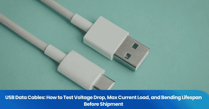
A "100W fast-charge USB-C cable" that cannot sustain 3 amps without overheating is not a minor product defect — it is a fire hazard and a device-destroyer in your customer's hands. USB cables are one of the most commonly counterfeited consumer electronics accessories shipped from China, and the gap between what is printed on the packaging and what is inside the jacket can be enormous. This guide walks through three key quality dimensions that importers must test before releasing a USB cable shipment: voltage drop under load, actual maximum current capacity, and mechanical bending lifespan at the strain relief joint. Each test is practical, can be performed on-site or in a qualified lab, and reveals failure modes that visual inspection will never catch.
Key Takeaways
- A USB cable's wire gauge (AWG) is the single largest determinant of voltage drop and current capacity. Fake cables claiming fast-charge capability routinely use 28 AWG power conductors when the application requires 20–24 AWG.
- The USB-IF's official bend test only specifies 100 cycles — far below real-world usage. Buyer-specified contracts should require 10,000-cycle bend testing at 120° arc to verify strain relief durability.
- USB Power Delivery cables above 60W require an E-Marker chip. Absence of this chip in a claimed high-wattage cable is grounds for immediate inspection failure, regardless of other results.
Why USB Cable Quality Failures Are Invisible Until They Cause Damage
The AWG Problem: What's Inside the Jacket Determines Everything
Wire gauge — measured in AWG (American Wire Gauge) — is the single most important variable in a USB cable's performance and safety. In the AWG system, a lower number means a thicker wire with lower resistance and higher current-carrying capacity. A 20 AWG power conductor handles 5A comfortably; a 28 AWG conductor in the same application creates dangerous levels of resistive heating. The problem for buyers is that AWG is invisible from the outside. A cable with a braided nylon jacket, gold-plated connectors, and a glossy box claiming "100W fast charge" may contain 28 AWG power wires that physically cannot support the advertised load.
The performance gap is not theoretical. Comparative testing has shown that a low-quality USB cable with undersized conductors delivered only 50mA of charging current from an 800mA-rated charger — just 6% of the adapter's rated output — while a correctly gauged cable from the same charger delivered 720mA. That is not a marginal difference; it is the difference between a phone charging in two hours and charging in sixteen.
For buyers sourcing cables at volume from China, the key AWG reference points are: 20–22 AWG for power conductors in cables rated ≥100W; 24 AWG for cables rated up to 60W; 28 AWG for data wires in USB 3.0 cables (twisted pairs); and 28/28 (all conductors 28 AWG) is a near-certain indicator of a charge-only, low-current cable being sold as something more capable.
The E-Marker Problem: Missing Chips in High-Wattage Claims
USB Type-C Power Delivery cables rated above 60W require an E-Marker chip — an electronic marker embedded in one of the connectors that communicates the cable's current rating and capabilities to the connected devices. Without an E-Marker, devices cannot safely negotiate power above 60W, regardless of what the cable's conductors could physically carry. E-Marker chips carry the cable's Vendor Data Object (VDO) information including data speed, current capacity, and power delivery specifications — and devices verify this data before negotiating higher power levels. A cable claiming 100W or 240W capability with a missing or fraudulent E-Marker is not just underperforming; it is creating conditions for unsafe power negotiation between the charger and device.
Inspectors can verify E-Marker presence using a USB Power Delivery tester that reads the cable's VDO data. The verification takes under a minute per sample and will immediately flag missing or spoofed chips. This check should be a mandatory pass/fail criterion on any inspection checklist for cables claiming to support Power Delivery above 60W.
Voltage Drop Testing: The Standard and What It Reveals
What Voltage Drop Is and Why It Matters
Voltage drop is the reduction in voltage measured between the input end and the output end of a cable under load. Every conductor has resistance; when current flows, that resistance causes voltage to fall along the cable's length. For USB charging, the specification governs how much drop is acceptable. The USB 2.0 specification permits a maximum cable voltage drop of 350mV, and bus-powered devices with captive cables must maintain Vdrop at or below this threshold. For USB-C Power Delivery applications, voltage drop has a direct relationship to charging efficiency: cables lose power as heat proportional to current squared times resistance, meaning that an undersized cable running at 5A generates four times the heat of the same cable running at 2.5A.
The practical test is straightforward. Using a USB power meter or inline tester, apply a known constant current load (2A for standard charging cables, 3A for fast-charge cables, 5A for full Power Delivery cables) and measure the voltage at the output end. For a 1-meter fast-charge cable at 3A, the measured output should remain above 4.65V from a 5V source — a drop greater than 350mV at the specified current indicates conductor resistance outside specification.
How to Run a Voltage Drop Check During Pre-Shipment Inspection
A USB multimeter with inline current measurement capability is the primary tool. For a batch inspection, the procedure runs as follows: select a random AQL sample per the order quantity, connect each cable between a stable 5V/3A power supply and a resistive load, measure output voltage under full load, and record pass or fail against the 350mV drop threshold. The test takes approximately 90 seconds per cable. A pass result at 3A load with cable resistance below 0.1 ohms ensures the voltage drop stays within 350mV — the key acceptance criterion for quality cables.
One important nuance: voltage drop is independent of the source voltage and depends only on current. This means a cable that passes at 5V/2A can still fail at 20V/5A if the Power Delivery current exceeds the conductor's capacity. For cables sold for laptop charging (where high-current PD scenarios are the primary use case), always test at the maximum rated current — not at a lower convenience current.
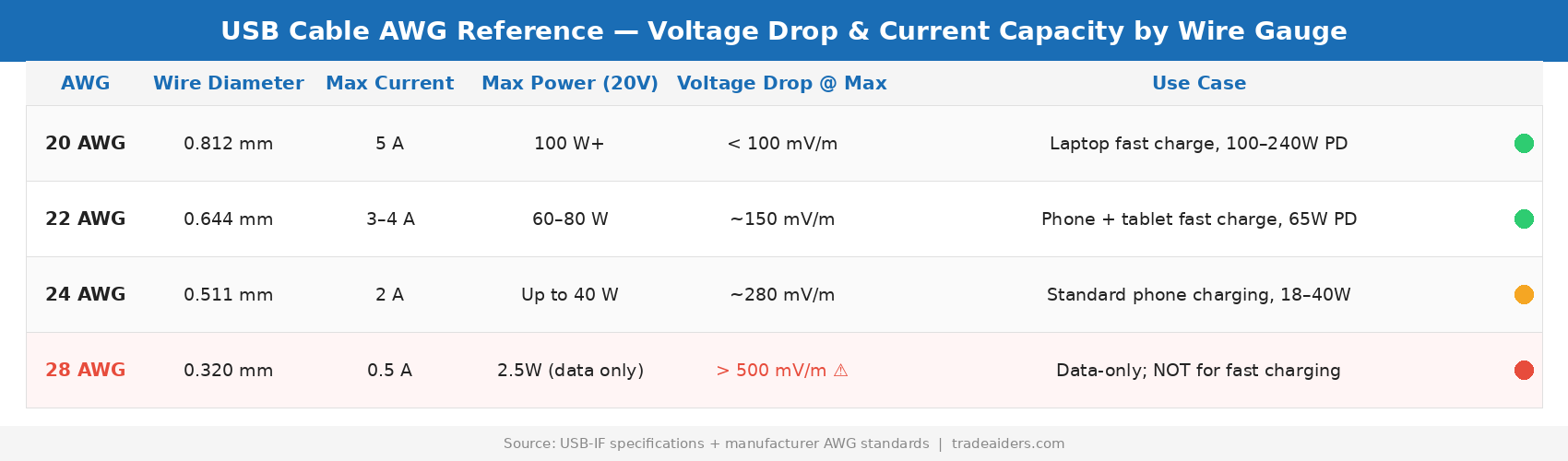
AWG reference chart for USB cable power conductors — voltage drop and current ratings by wire gauge.
Maximum Current Load Testing: What Factories Don't Want You to Check
The Current Rating Gap Between Label and Reality
Cable current ratings on Chinese factory spec sheets frequently cite the theoretical rating of the connector standard rather than the actual sustained current capability of the specific cable being shipped. A USB-C connector is rated for 5A in the USB specification. That does not mean every USB-C cable can carry 5A — it means the connector housing was designed to that standard. The actual cable's maximum safe current depends on conductor cross-section, conductor material quality, and insulation heat tolerance.
Sustained current testing exposes this gap directly. The protocol: charge a load at the cable's rated current for a minimum of 30 minutes while measuring the cable's surface temperature at the midpoint and at the strain relief near each connector. A properly rated cable should not exceed 60°C surface temperature under rated load. Temperature above 70°C indicates the conductors are operating in thermal stress range — the cable will degrade accelerating over its product life and may pose a burn risk in consumer hands.
AWG-to-Current Reference Table for Inspection Planning
| Power Wire AWG | Max Recommended Current | Max Supported Wattage (20V) | Suitable Cable Length |
|---|---|---|---|
| 20 AWG | 5A | 100W+ | Up to 2m |
| 22 AWG | 3–4A | 60–80W | Up to 1.5m |
| 24 AWG | 2A | Up to 40W | Up to 2m |
| 28 AWG | 0.5A | 2.5W (data/low-power only) | Up to 1m |
When a cable marketed as a "fast charger" is cross-sectioned during inspection and the power conductors measure 28 AWG, the entire batch should be quarantined. This finding — undersized conductors in a labeled fast-charge cable — is not a minor defect. It is a safety non-conformance that justifies rejection under AQL critical defect criteria. The distinction between critical, major, and minor defects matters here: a cable that can damage the end user's device or pose a fire hazard must be classified as critical, with an AQL acceptance number of zero.
Bending Lifespan Testing: Where Most Cheap Cables Fail
Why the Official USB-IF Bend Standard Is Insufficient
The strain relief — the reinforced section where the cable meets the connector housing — is the failure point in the overwhelming majority of cable field failures. Cables fray, short, or lose conductivity at this joint because every time the cable bends near the connector, the copper conductors flex. Over thousands of cycles, metal fatigue accumulates. The question is not whether the cable will eventually fail at the strain relief; it is how many cycles it can sustain before electrical integrity degrades.
The official USB-IF Type-C flex/bend test in EIA 364-41 specifies only 100 bend cycles. A consumer-electronics industry test using 10,000 bend cycles at 120° arc (60° each side of center) at 30 cycles/minute found that the majority of CE-marked cables sold on popular e-commerce platforms failed to maintain electrical compliance even at this more realistic threshold. 100 cycles represents a matter of weeks for an average user who plugs in their phone daily; 10,000 cycles is closer to two to three years of real-world use.
How to Specify Bending Tests in Purchase Orders
Buyers who do not specify bend-test requirements in their purchase orders will receive cables built to the minimum standard — which, for most Chinese cable factories, means passing the 100-cycle USB-IF specification and nothing more. To protect product quality and reduce return rates, specify the following in your PO or product quality agreement: bend test method (EIA 364-41 or equivalent); number of cycles (minimum 5,000 for budget products, 10,000 for premium lines); bend angle (120° total, 60° each side of center); applied load at free end (100g is common); pass criterion (no loss of continuity, no increase in resistance above 10% of baseline, no visible conductor exposure). Request the factory's bend test records from recent production runs. A factory that cannot produce bend test data from the current production batch has not performed the test.
What an On-Site Rapid Bend Assessment Looks Like
During pre-shipment inspection, a full machine-based 10,000-cycle bend test is not practical — it takes hours per sample. But inspectors can run an accelerated manual assessment that flags the most obvious failures. The procedure: select 10 samples from the AQL lot, flex each cable 100 times by hand at the strain relief near each connector using a 90° bend, then connect each cable to a USB power meter and verify continuity and voltage drop against baseline. Any cable that shows increased resistance (drop in measured current at constant load) or intermittent continuity has a marginal strain relief that will fail in the field. This rapid screen catches the worst cases without lab equipment and typically takes 20–30 minutes per lot.
For comprehensive bending lifespan data, coordinate third-party laboratory testing through TradeAider's product testing service. Machine-based cyclic bend testing to buyer-defined specifications generates the data needed both for product development and for quality records that protect the buyer in the event of field failures.
Building a USB Cable Inspection Checklist
What a Complete Pre-Shipment Check Covers
A robust USB cable inspection checklist for importers should integrate all three test categories discussed above, alongside standard visual and dimensional checks. The most common issues in quality control inspections — unclear specifications, human error, and missing test standards — are particularly acute for USB cables because the product is cheap, small, and easy to underspec at the factory level.
Visual and physical checks include: connector housing integrity (no cracks, misalignment, or loose fit); strain relief flexibility and uniform taper at both ends; jacket material quality (braided vs. PVC, outer diameter consistent with spec); and label accuracy (AWG printed on cable if specified, USB-IF certification number visible if claimed). Electrical checks cover: voltage drop at rated current; E-Marker VDO verification for PD cables above 60W; wire gauge cross-section verification on a destructive sample (one unit per batch minimum); and continuity check on all conductors (data lines and power lines). Mechanical checks involve the rapid bend assessment protocol described above, plus connector mating force (should require 5–10N to seat, not fall in loosely or require excessive force). Document review covers USB-IF certification records if applicable, and test reports for bend/flex testing from the current production run.
The TradeAider pre-shipment inspection for consumer electronics covers all these categories on-site, with a real-time report accessible during the inspection. Inspectors can flag an E-Marker failure at 10am and the buyer can immediately redirect the inspection to cross-section additional samples — before the container is sealed. Use the Inspection Charge Calculator to plan costs for your order volume.
Frequently Asked Questions
How can I tell if a USB-C cable has an E-Marker chip without lab equipment?
An E-Marker chip can be detected using a USB-C power tester that supports Power Delivery protocol analysis. These testers — available for under $50 — display the cable's VDO data when connected between a PD-capable charger and a device. If the tester shows no VDO data on a cable claimed to support above 60W, the E-Marker is missing. A visual check alone cannot reveal E-Marker presence; the chip is inside the connector housing.
What does a voltage drop of more than 350mV actually mean in practice?
A 350mV drop at 3A means the cable is dissipating over 1 watt as heat — a small but measurable warming in a 1-meter cable. At 5A, the same resistively lossy cable dissipates nearly 2 watts, enough to make the cable noticeably warm during sustained charging and to reduce charging efficiency by several percent. Beyond the efficiency loss, sustained thermal stress accelerates insulation degradation and conductor oxidation, shortening the cable's operational life.
Can a cable pass visual and hand-feel inspection and still fail electrical tests?
Yes — consistently. Undersized copper conductors feel softer and more flexible than correctly gauged cables, which can actually make a fraudulent cable seem like a "premium flexible" product to a buyer who handles it. The outer jacket, connector finish, and mold quality can all be high-grade while the internal conductors are undersized. This is why electrical testing, not visual inspection, is the authoritative check for USB cable quality.
Should I require different inspection standards for USB-A vs. USB-C cables?
Yes, significantly so. USB-A cables are governed by older, lower-power specifications (typically up to 2.1A), so voltage drop and current load expectations are more lenient. USB-C cables, especially those sold for Power Delivery or fast charging, must be evaluated against the specific wattage claim on the product. A 100W USB-C cable requires E-Marker verification, 20 AWG minimum power conductors, and a voltage drop test at 5A. Applying USB-A inspection standards to a fast-charge USB-C product will miss the most commercially significant failure modes.

Похожие статьи


Развивайте свой бизнес с услугами TradeAider
Нажмите кнопку ниже, чтобы войти непосредственно в систему услуг TradeAider. Простые шаги от бронирования и оплаты до получения отчетов легко выполнить.